Download
1 / 27
280 likes | 433 Vues
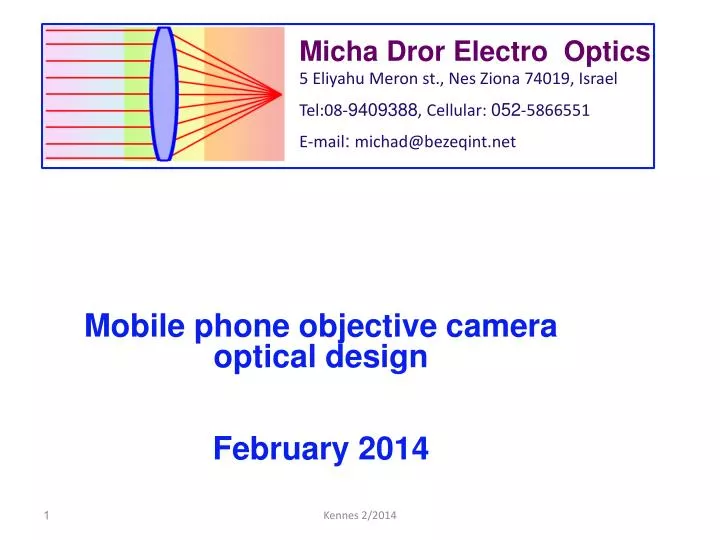
Micha Dror Electro Optics 5 Eliyahu Meron st ., Nes Ziona 74019, Israel Tel:08- 9409388 , Cellular: 052 -5866551 E-mail : michad@bezeqint.net. Mobile phone objective camera optical design February 2014. Micha Dror Electro Optics 5 Eliyahu Meron st ., Nes Ziona 74019, Israel

E N D
MichaDror Electro Optics • 5 EliyahuMeronst., NesZiona 74019, Israel • Tel:08-9409388, Cellular: 052-5866551 • E-mail: michad@bezeqint.net • Mobile phone objective camera optical design February 2014 Kennes 2/2014
MichaDror Electro Optics • 5 EliyahuMeronst., NesZiona 74019, Israel • Tel:08-9409388, Cellular: 052-5866551 • E-mail: michad@bezeqint.net Mobile phone camera objective unique requirements: Small packaging and cost effectiveness. Small packaging dimensions - mobile phones tend to be as thin as possible. This leads to total optics length (first optical surface to image sensor) of 4-5mm. Kennes 2/2014
MichaDror Electro Optics • 5 EliyahuMeronst., NesZiona 74019, Israel • Tel:08-9409388, Cellular: 052-5866551 • E-mail: michad@bezeqint.net In order to reduce optics length, small pixel size is needed, that reduces image sensor format, which leads in turn to reduced focal length and system length: f = D/(2*tan (ϴ/2)) where: D - image sensor diagonal, ϴ - field of view. Usually the field of view (ϴ) is about 68° and the image sensor diagonal (D) is 5.5mm, that lead to a focal length (f) of 4.08mm, which can be designed in a total length of less than 5mm. Kennes 2/2014
MichaDror Electro Optics • 5 EliyahuMeronst., NesZiona 74019, Israel • Tel:08-9409388, Cellular: 052-5866551 • E-mail: michad@bezeqint.net Resolution of optics is measured in lp/mm. 1.1μm pixel, smallest cycle is a black and white pixels. 1.1μm pixel the cycle will be 2.2μm. spatial frequency of 1000/2.2 = 455lp/mm. This cutoff frequency is called the Nyquist frequency (Ny). Kennes 2/2014
MichaDror Electro Optics • 5 EliyahuMeronst., NesZiona 74019, Israel • Tel:08-9409388, Cellular: 052-5866551 • E-mail: michad@bezeqint.net MTF specification of optics refer to this frequency, or lower frequencies: half Nyquist frequency (Ny/2) of two black and two white pixels, 4.4μm for a 1.1 pixel size: 1000/4.4μm = 227lp/mm. Ny/3 = 152lp/mm Kennes 2/2014
MichaDror Electro Optics • 5 EliyahuMeronst., NesZiona 74019, Israel • Tel:08-9409388, Cellular: 052-5866551 • E-mail: michad@bezeqint.net Low cost phones use a fixed focus objective. Smart phones usually use a focus mechanism, based on voice coil magnetic (VCM) technology: a motor made of a coil and a permanent magnet. These modules are compact and cheap. New technologies are emerging: Corephotonics (Magnetic reluctance auto focus actuator) MEMS type (Tessera) and others. Kennes 2/2014
Low Until recently some mobile phones employed Extended Depth Of Focus (EDOF) technology. This technology replaces the need of moving focus mechanism. The optics is designed to have lower MTF level, but with higher MTF for objects out of focus. Image processing can improve the overall camera MTF and imitates the mechanical moving lens focusing. This method has the big advantage of non moving parts but the performance is not as good as the mechanical focusing. • MichaDror Electro Optics • 5 EliyahuMeronst., NesZiona 74019, Israel • Tel:08-9409388, Cellular: 052-5866551 • E-mail: michad@bezeqint.net Until recently some mobile phones employed Extended Depth Of Focus (EDOF) technology. This technology replaces the need of moving focus mechanism. The optics is designed to have lower MTF level, but with higher MTF for objects out of focus. Kennes 2/2014
MichaDror Electro Optics • 5 EliyahuMeronst., NesZiona 74019, Israel • Tel:08-9409388, Cellular: 052-5866551 • E-mail: michad@bezeqint.net Image processing can improve the overall camera MTF and imitates the mechanical moving lens focusing. This method has the big advantage of non moving parts but the performance is not as good as the mechanical focusing. Kennes 2/2014
MichaDror Electro Optics • 5 EliyahuMeronst., NesZiona 74019, Israel • Tel:08-9409388, Cellular: 052-5866551 • E-mail: michad@bezeqint.net Optical design considerations: F-number - a low F-number improves performance at dim light. On the other hand it decreases the depth of field, the sensitivity to focusing error and the sensitivity to manufacturing errors. Most cameras usually have an F-number value of 2.4 Focal length - derived from the image sensor format size and field of view requirements. Kennes 2/2014
Lateral color - Usually the requirement is not greater than 2 pixels. Practically most designs meet 1 pixel lateral color. CRA (Chief Ray Angle) - increases with field angle. In order for the sensor to collect the light efficiently, a micro-lens array focuses the light on the pixel active area. The lens array is optimized for specific chief ray angles defined by the camera manufacturer. Usually this data is dictated for the optical design as the tendency is to use an on the shelf camera and to avoid a change in camera production line due to the optical design. Manufacture guide lines - the optical design should take into account manufacturer guidelines that may differ from one manufacturer to another: optical materials preferred by the manufacturer, maximum surface slope angles, minimal edge/center thickness, etc. • MichaDror Electro Optics • 5 EliyahuMeronst., NesZiona 74019, Israel • Tel:08-9409388, Cellular: 052-5866551 • E-mail: michad@bezeqint.net Distortion - Usually smaller than 2% and TV distortion (departure from a line object) Less than 1%. Usually the distortion is negative to improve relative illumination. Kennes 2/2014
Lateral color - Usually the requirement is not greater than 2 pixels. Practically most designs meet 1 pixel lateral color. CRA (Chief Ray Angle) - increases with field angle. In order for the sensor to collect the light efficiently, a micro-lens array focuses the light on the pixel active area. The lens array is optimized for specific chief ray angles defined by the camera manufacturer. Usually this data is dictated for the optical design as the tendency is to use an on the shelf camera and to avoid a change in camera production line due to the optical design. Manufacture guide lines - the optical design should take into account manufacturer guidelines that may differ from one manufacturer to another: optical materials preferred by the manufacturer, maximum surface slope angles, minimal edge/center thickness, etc. • MichaDror Electro Optics • 5 EliyahuMeronst., NesZiona 74019, Israel • Tel:08-9409388, Cellular: 052-5866551 • E-mail: michad@bezeqint.net Relative illumination - ideal lens it decreases with field of view according to cosine fourth law. For a 34degree half field the cosine is 0.829, which leads to a 47% relative illumination at the field edge. Usually the requirement is not less the 50% (relative to field of view center). This can be increased above theoretical limit by using negative distortion, which shrinks the image at the field edge and therefore increases light concentration. Kennes 2/2014
Lateral color - Usually the requirement is not greater than 2 pixels. Practically most designs meet 1 pixel lateral color. CRA (Chief Ray Angle) - increases with field angle. In order for the sensor to collect the light efficiently, a micro-lens array focuses the light on the pixel active area. The lens array is optimized for specific chief ray angles defined by the camera manufacturer. Usually this data is dictated for the optical design as the tendency is to use an on the shelf camera and to avoid a change in camera production line due to the optical design. Manufacture guide lines - the optical design should take into account manufacturer guidelines that may differ from one manufacturer to another: optical materials preferred by the manufacturer, maximum surface slope angles, minimal edge/center thickness, etc. • MichaDror Electro Optics • 5 EliyahuMeronst., NesZiona 74019, Israel • Tel:08-9409388, Cellular: 052-5866551 • E-mail: michad@bezeqint.net Lateral color - Usually the requirement is not greater than 2 pixels. Practically most designs meet 1 pixel lateral color. Kennes 2/2014
Lateral color - Usually the requirement is not greater than 2 pixels. Practically most designs meet 1 pixel lateral color. CRA (Chief Ray Angle) - increases with field angle. In order for the sensor to collect the light efficiently, a micro-lens array focuses the light on the pixel active area. The lens array is optimized for specific chief ray angles defined by the camera manufacturer. Usually this data is dictated for the optical design as the tendency is to use an on the shelf camera and to avoid a change in camera production line due to the optical design. Manufacture guide lines - the optical design should take into account manufacturer guidelines that may differ from one manufacturer to another: optical materials preferred by the manufacturer, maximum surface slope angles, minimal edge/center thickness, etc. • MichaDror Electro Optics • 5 EliyahuMeronst., NesZiona 74019, Israel • Tel:08-9409388, Cellular: 052-5866551 • E-mail: michad@bezeqint.net CRA (Chief Ray Angle) - increases with field angle. In order for the sensor to collect the light efficiently, a micro-lens array focuses the light on the pixel active area. The lens array is optimized for specific chief ray angles defined by the camera manufacturer. Usually this data is dictated for the optical design as the tendency is to use an on the shelf camera and to avoid a change in camera production line due to the optical design Kennes 2/2014
Lateral color - Usually the requirement is not greater than 2 pixels. Practically most designs meet 1 pixel lateral color. CRA (Chief Ray Angle) - increases with field angle. In order for the sensor to collect the light efficiently, a micro-lens array focuses the light on the pixel active area. The lens array is optimized for specific chief ray angles defined by the camera manufacturer. Usually this data is dictated for the optical design as the tendency is to use an on the shelf camera and to avoid a change in camera production line due to the optical design. Manufacture guide lines - the optical design should take into account manufacturer guidelines that may differ from one manufacturer to another: optical materials preferred by the manufacturer, maximum surface slope angles, minimal edge/center thickness, etc. • MichaDror Electro Optics • 5 EliyahuMeronst., NesZiona 74019, Israel • Tel:08-9409388, Cellular: 052-5866551 • E-mail: michad@bezeqint.net Manufacture guide lines - the optical design should take into account manufacturer guidelines that may differ from one manufacturer to another: optical materials preferred by the manufacturer, maximum surface slope angles, minimal edge/center thickness, etc. Kennes 2/2014
Tolerance analysis - This market is sensitive to cost and to yield. Therefore an extensive effort is invested in order to reduce design sensitivity to manufacture/assembly errors. Extensive simulations are made to estimate the production yield and to finding the optimal tradeoff between performance and yield. • MichaDror Electro Optics • 5 EliyahuMeronst., NesZiona 74019, Israel • Tel:08-9409388, Cellular: 052-5866551 • E-mail: michad@bezeqint.net • Manufacture technologies: • Aspheric plastic injection molded optics. The plastic is melted to liquid (relatively low temperature of about 160°C) and injected to a mold. As plastic is less rigid and stable than glass, this technology is applicable for small lenses such as mobile phone optics. Kennes 2/2014
Lateral color - Usually the requirement is not greater than 2 pixels. Practically most designs meet 1 pixel lateral color. CRA (Chief Ray Angle) - increases with field angle. In order for the sensor to collect the light efficiently, a micro-lens array focuses the light on the pixel active area. The lens array is optimized for specific chief ray angles defined by the camera manufacturer. Usually this data is dictated for the optical design as the tendency is to use an on the shelf camera and to avoid a change in camera production line due to the optical design. Manufacture guide lines - the optical design should take into account manufacturer guidelines that may differ from one manufacturer to another: optical materials preferred by the manufacturer, maximum surface slope angles, minimal edge/center thickness, etc. Tolerance analysis - This market is sensitive to cost and to yield. Therefore an extensive effort is invested in order to reduce design sensitivity to manufacture/assembly errors. Extensive simulations are made to estimate the production yield and to finding the optimal tradeoff between performance and yield. • MichaDror Electro Optics • 5 EliyahuMeronst., NesZiona 74019, Israel • Tel:08-9409388, Cellular: 052-5866551 • E-mail: michad@bezeqint.net Larger lenses are produced from glass. Due to the glass high melting temperature, the glass is heated to softening temperature and than compressed by a mold (compression molding). Plastic molding is less expensive than glass molding. On the other hand glass has a wider optical choice of refractive index/Abbe properties, which improves the optical design. Kennes 2/2014
Lateral color - Usually the requirement is not greater than 2 pixels. Practically most designs meet 1 pixel lateral color. CRA (Chief Ray Angle) - increases with field angle. In order for the sensor to collect the light efficiently, a micro-lens array focuses the light on the pixel active area. The lens array is optimized for specific chief ray angles defined by the camera manufacturer. Usually this data is dictated for the optical design as the tendency is to use an on the shelf camera and to avoid a change in camera production line due to the optical design. Manufacture guide lines - the optical design should take into account manufacturer guidelines that may differ from one manufacturer to another: optical materials preferred by the manufacturer, maximum surface slope angles, minimal edge/center thickness, etc. Tolerance analysis - This market is sensitive to cost and to yield. Therefore an extensive effort is invested in order to reduce design sensitivity to manufacture/assembly errors. Extensive simulations are made to estimate the production yield and to finding the optimal tradeoff between performance and yield. • MichaDror Electro Optics • 5 EliyahuMeronst., NesZiona 74019, Israel • Tel:08-9409388, Cellular: 052-5866551 • E-mail: michad@bezeqint.net • Wafer level, low cost technology - usually for a VGA camera. This technology uses UV replication technology, where a liquid polymer is dispensed on the wafer and the lenses are imprinted by using a transparent stamp or mold and UV-light for curing. This method allows the manufacture of a large scale of lens arrays with a sub-micron surface accuracy on a 10’’ wafer size. A mold with lens stamps is filled with liquid polymer. This mold is covered by glass wafer: Kennes 2/2014
Lateral color - Usually the requirement is not greater than 2 pixels. Practically most designs meet 1 pixel lateral color. CRA (Chief Ray Angle) - increases with field angle. In order for the sensor to collect the light efficiently, a micro-lens array focuses the light on the pixel active area. The lens array is optimized for specific chief ray angles defined by the camera manufacturer. Usually this data is dictated for the optical design as the tendency is to use an on the shelf camera and to avoid a change in camera production line due to the optical design. Manufacture guide lines - the optical design should take into account manufacturer guidelines that may differ from one manufacturer to another: optical materials preferred by the manufacturer, maximum surface slope angles, minimal edge/center thickness, etc. • MichaDror Electro Optics • 5 EliyahuMeronst., NesZiona 74019, Israel • Tel:08-9409388, Cellular: 052-5866551 • E-mail: michad@bezeqint.net • Wafer level, low cost technology - usually for a VGA camera. This technology uses UV replication technology, where a liquid polymer is dispensed on the wafer and the lenses are imprinted by using a transparent stamp or mold and UV-light for curing. This method allows the manufacture of a large scale of lens arrays with a sub-micron surface accuracy on a 10’’ wafer size. A mold with lens stamps is filled with liquid polymer. This mold is covered by glass wafer: Kennes 2/2014
MichaDror Electro Optics • 5 EliyahuMeronst., NesZiona 74019, Israel • Tel:08-9409388, Cellular: 052-5866551 • E-mail: michad@bezeqint.net Removing the mold after UV curing Repeating process on the opposite wafer side: Kennes 2/2014
MichaDror Electro Optics • 5 EliyahuMeronst., NesZiona 74019, Israel • Tel:08-9409388, Cellular: 052-5866551 • E-mail: michad@bezeqint.net Removing the mold after UV curing Combining several wafers, to create multiple lens system and inserting spacers between wafers (for simplicity only edge spacers are shown and not all the spacers needed between all lenses), and then cutting all the array into single channels (dashed line). See a real design in the last design example. Kennes 2/2014
MichaDror Electro Optics • 5 EliyahuMeronst., NesZiona 74019, Israel • Tel:08-9409388, Cellular: 052-5866551 • E-mail: michad@bezeqint.net 3 Mpixel, F2.0, 2.9mm sensor diagonal Kennes 2/2014
MichaDror Electro Optics • 5 EliyahuMeronst., NesZiona 74019, Israel • Tel:08-9409388, Cellular: 052-5866551 • E-mail: michad@bezeqint.net 3 Mpixel, F2.0, 2.9mm sensor diagonal Kennes 2/2014
MichaDror Electro Optics • 5 EliyahuMeronst., NesZiona 74019, Israel • Tel:08-9409388, Cellular: 052-5866551 • E-mail: michad@bezeqint.net 8 Mpixel, F2.4, 4.54mm sensor diagonal Kennes 2/2014
MichaDror Electro Optics • 5 EliyahuMeronst., NesZiona 74019, Israel • Tel:08-9409388, Cellular: 052-5866551 • E-mail: michad@bezeqint.net 8 Mpixel, F2.4, 4.54mm sensor diagonal Kennes 2/2014
MichaDror Electro Optics • 5 EliyahuMeronst., NesZiona 74019, Israel • Tel:08-9409388, Cellular: 052-5866551 • E-mail: michad@bezeqint.net 3 Mpixel, F2.6, 4.6mm sensor diagonal, wafer level design Light blue plates are wafer glass plates. Kennes 2/2014
MichaDror Electro Optics • 5 EliyahuMeronst., NesZiona 74019, Israel • Tel:08-9409388, Cellular: 052-5866551 • E-mail: michad@bezeqint.net 3 Mpixel, F2.6, 4.6mm sensor diagonal, wafer level design Kennes 2/2014
MichaDror Electro Optics • 5 EliyahuMeronst., NesZiona 74019, Israel • Tel:08-9409388, Cellular: 052-5866551 • E-mail: michad@bezeqint.net Applicable patents: • US 7079330 B2 - 4 lens design • US 8305699 B2 - Wafer level design Kennes 2/2014