Download
1 / 30
380 likes | 736 Vues
Ph. KUBIK, A. MEYGRET, E. BRETON, F. MASSON M. PAUSADER, D. LEGER, L. POUTIER. O. HAGOLLE, A. MEYGRET M. DINGUIRARD, D. LEGER F. VIALLEFONT, R. GACHET AC. DE GAUJAC. P. HENRY, X. BRIOTTET M. DINGUIRARD, D. LEGER AC. DE GAUJAC, P. GIGORD.

E N D
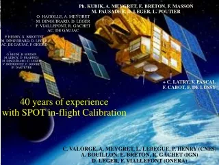
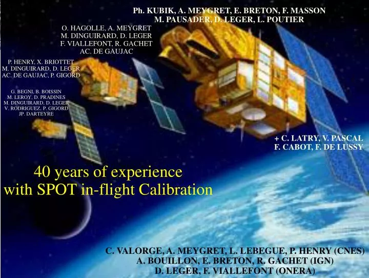
Ph. KUBIK, A. MEYGRET, E. BRETON, F. MASSONM. PAUSADER, D. LEGER, L. POUTIER O. HAGOLLE, A. MEYGRETM. DINGUIRARD, D. LEGERF. VIALLEFONT, R. GACHETAC. DE GAUJAC P. HENRY, X. BRIOTTETM. DINGUIRARD, D. LEGERAC. DE GAUJAC, P. GIGORD G. BEGNI, B. BOISSINM. LEROY, D. PRADINESM. DINGUIRARD, D. LEGERV. RODRIGUEZ, P. GIGORDJP. DARTEYRE + C. LATRY, V. PASCALF. CABOT, F. DE LUSSY 40 years of experience with SPOT in-flight Calibration C. VALORGE, A. MEYGRET, L. LEBEGUE, P. HENRY (CNES)A. BOUILLON, E. BRETON, R. GACHET (IGN) D. LEGER, F. VIALLEFONT (ONERA)
Overview • SPOT system overview • SPOT satellites • SPOT system • Geometric calibration and quality assessment • Geolocation model and accuracy • Internal orientation • Image deformation quality assessment • Radiometric calibration and quality assessment • Radiometric model • Normalization • Absolute calibration • Spatial Resolution • Refocusing • MTF assessment • Summary
SPOT system overview • First generation : 2 identical instruments called HRV: 10m Pan - 20 m multispectral; steering mirror (+/-27°) • SPOT 1: launched 22 February, 1986 put on a 560 km orbit in November 2003. Re-entry in 2019 • SPOT 2: launched 22 January, 1990 no more on-board recording since October, 1993 • SPOT 3: launched 26 September, 1993 failed on 14 November, 1996 • SPOT 4: launched 24 March, 1998 • New platform, same resolution • New 20m SWIR band (HRVIR) • VEGETATION payload • SPOT 5: launched 4 May, 2002 • Resolution (HRG): 5 m in panchromatic mode, 10 m in spectral mode 2,5 m in panchromatic mode through processing (THR) • Passengers: VEGETATION-2, HRS (High resolution stereo camera), Stellar Sensor • Current operational constellation: SPOT2, SPOT4 and SPOT5 • Cumulated life on-orbit: 16 + 14 + 3 + 5.5 + 1.5 = 40 years ;-)
Satellite Operations and Control Center Network of Direct Receiving Stations Image QualityExpertise Center Processing andArchiving Center ProgrammingCenter SPOT system overview • System description: • 832km Sun-synchronous orbit; 26 days repeat cycle900 km wide corridor, daily access • Operational architecture
SPOT system overview • The Image Quality Expertise Center is in charge ofall in-flight activities regarding Image Quality: • Determination of the optimal on-board parameters (focus, radiometric gains, compression parameters…) • Elaboration of the best ground-processing parameters (normalization parameters, interior orientation…), validation and transmission to the processing stations • Periodic assessment of Image Quality Budgets (wrt specifications): « SPOT Image Quality Performances » issued every year, edited by Spotimage, provided to their customers • Analysis and resolution of any image quality problem occuring in-flight • This implies specific capacities: • Dedicated programmations of the payloads (even non-nominal) • Management of calibration sites and means • Dedicated facility, computers, operational interfaces… • This Center is operated by technicians and engineers from CNES, IGN and ONERA (up to 20 people during commissioning phases, 5 for routine operations)
Geometric Calibration • Geolocation model Calibration: • GCP database • Established since SPOT1, refurbished for SPOT5 (improved resolution, need of better accuracy) • Planimetric precision: better than 5m for most GCPs • Sites covering at least 120 km x 120 km (HRS) + France • Special emphasis on the scattering of the location sites around the world • One bundle block adjustment per calibration site involving all calibration acquisitions • Systematic programming of both HRV/IR/G + HRS • Between 10 and 20 GCP per image • More than 100 images per site in routine phases: robust estimations • Possibility to correct for erroneous GCP coordinates • Identification of correction parameters for each acquisition • Yaw, pitch and roll biases are then analysed in terms of calibration, for each instrument, with respect to the steering mirror position, latitude, …. • Each new acquisition over a given location site is then added to the corresponding block
Location sites over the world Main sites: 12 Secundary sites: 4 No more used
mirror’s axis wedging defaults levelness default between mirror axis and mirror plane Real normal Normal for a perfect mirror mirror ’s pointing angle Geometric Calibration • Steering mirror viewing model:
In yaw In pitch In roll Orbital trends before correction Geometric Calibration • Exterior orientation calibration: • After steering mirror calibration: remaining errors translated into biases between instrument and AOCS reference frames • Interest of the world-wide scattering of our sites: • We quickly discovered an orbital variation of these « biases », the same for each instrument on-board SPOT5 • After analysis, due to a wrong reference date in the stellar sensor… • Constant biaises after correction of this on-board problem
Geometric Calibration • Geolocation accuracy assessment: • Done simultaneously with calibration activities • Stringent SPOT5 specifications concerning geolocation accuracy: • 50m CE RMS for HRS • 15m CE90 after bundle block adjustment without GCPs for Reference3D => intensive routine monitoring: • at least, each site must be acquired during each repeat cycle (26 days) • quasi-real time exploitation of these images
Geometric Calibration • Internal orientation: • Absolute method • panchromatic and multispectral reference bands (HMA and B2) • each HRS band • comparison image / reference • Relative method • THR mode (HMA/HMB bands) • Multispectral mode (B1/B2/B3/SWIR bands) • Relative panchromatic/multispectral (P/XS) • comparison of pairs of simultaneous images • Quality assessment: • Made simultaneously: same methods, different acquisitions, checked on corrected images
Reference SPOT 5 Geometric Calibration • Absolute internal orientation calibration: • Reference data: Manosque test-site • Aerial cover of a 60 km 7 km area at 1.50 m resolution with 80% overlap • Triangulation: 0.40 m. accuracy • Aerial digital surface model at 1 m resolution • Method • each aerial image is projected into SPOT5 image geometry (taking the MTF into account) • a fine image matching process measures differences between SPOT and the Reference • Filtering and averaging to get each detector orientation • Final modelling of these curves: • Drift of along-track orientation = yaw • Drift of across-track orientation = magnification • Higher degree tendancies = distortion
Geometric Calibration • Absolute internal orientation calibration: • Corrections achieved: • Magnification of each instrument • Relative yaw: HRS1/HRS2, HRG1/HRG2 and P/XS • Optical distortion: up to fifth degree polynomials • After calibration: residuals < 15 cm RMS(limitation due to the reference)
Use of a phased pair to determine the influence of a steering mirror move Geometric Calibration • Image deformation quality assessment: • Dynamic perturbations monitoring • Dynamic perturbations: inertial wheels, magnetic tape recorder (SPOT1-4), steering mirror, attitude restitution errors • Specific programmations: phased pairs (26 days time lag => same viewing conditions), Image Quality mode (simultaneous image of both HRV/IR/G), autotest (SPOT5, mirror in auto-collimation position) • Dense image matching + line-wise averaging => profile vs time • First conducted on SPOT1 as technology experiments (87) • Nominal activity since SPOT2
Geometric Calibration Use of a IQ couple to determine the steering mirror stabilization time Autotest pattern Use of the autotest for the same purpose: only one acquisition during night
Geometric Calibration • Image deformation quality assessment: • Length distortion assessment: • Conducted along with geolocation activities, using the same GCPs • Computed for each pair of GCP by comparing real/modelled distances • Analysis as function of orientation and length • Planimetric accuracy assessment: • Location accuracy after bundle block adjustment with GCP • Can be assessed with high precision GCPs (residual analysis) • Can be assessed along with altimetric accuracy (need for reference DEM) • Altimetric accuracy assessment: • Performed by value-added producers: IGN & ISTAR • Operational production capacity: optimal conditions, completeness… • Crucial point = reference DEM • HRS SAP initiative under ISPRS framework
C(k,n,b,m) g A(k) g(k,n,b) (k,b) G(m,k) R() 8-bits Rad ADC Amplification Optics & Read -out X(k,n,b,m) filters register (b) Detector (n) Absolute calibration Normalization Radiometric Calibration • Radiometric model: • Push-broom sensors => same model for all HRV, HRVIR, HRG, HRS X(k,n,b,m)=R[A(k).G(m,k)g(k,n,b).g(k,b).Rad(k,n,b)+C(k,n,b,m)]
Radiometric Calibration • Normalization • Normalized digital count: • Dark currents calibration: • Steering mirror in auto-collimation position (HRV, HRVIR, HRG) or night-acquisitions (HRS) • Obtained for each detector of each spectral band with each amplification gain by averaging its digital counts • Short term variation monitoring: 10 minute images • Medium term variation monitoring: one acquisition per week, then per month • Difficult case: SWIR band (high increases due to proton collisions)=> updated every week
Radiometric Calibration • Normalization • Inter-detector coefficients calibration • Problems with on-board lamp (steering mirror positioning accuracy) • Use of quasi-uniform landscapes: snowy expanses • Operationally heavy: 10% success (wheather, non-uniformity) • Correction of Solar incidence before averaging Greenland (summer) Antarctic (winter)
IA LF E/O HF Radiometric Calibration • Normalization quality assessment: • Made on uniform, normalized images: average line • Different criteria: • High Frequency • Low Frequency • Inter-Array • Even-Odd detectors • < 0.3 % for each
Radiometric Calibration • Signal-to-Noise Ratio (SNR) assessment: • Column-wise Noise: • Use of on-board lamp (SPOT1-4) • Use of quasi-uniform sites with 2 simultaneous acquisitions (to separate instrumental noise from landscape signal) • Noise model: • Physical understanding of noise sources (signal noise, digitization…) • Simple model: • Allows comparison of sensors in a common reference configuration • Line-wise Noise: cf. normalization qualityassessment • Image-Noise: combination of the twoprevious noises
Radiometric Calibration • Absolute Calibration: • Operational use of many different methods • Important for users, but also for amplification gain prediction G(m,k) • Gain calibration using IQ mode • SPOT Histogram DataBase (started in 87) • Stores every cloud-free scene histogram on a 120km x 120 km grid • Gives statistically significant estimation of observed radiances • Monthly average used to predict optimal amplification gains
Radiometric Calibration • Absolute Calibration: on-board calibration systems • Easy to use => frequent estimations • On-board lamp: not absolute but temporal variations monitoring
Radiometric Calibration • Absolute Calibration: on-board calibration systems • Sun-sensor • Optical fibers (48 for HRV, 24 for HRVIR) projecting solar radiance onto some detectors of each spectral band • Highly difficult to characterize before launch • On-orbit variation of fibers transmission • Successful only for SPOT4, abandoned for SPOT5… Eo(): spectral solar illumination u(t): Earth-Sun distance variation o(j): solid angle of fiber j TFIB: transmission of fiber j TBE(): spectral transmission of the calibration unit Sk(): spectral sensitivity of channel k
Radiometric Calibration • Absolute Calibration: use of specific landscapes • Rayleigh scattering • For short wavelengths (B1, B2) • Specific viewing conditions (clear ocean, off-nadir viewing) • Use of B3 for aerosol optical thickness estimation • Use of meteorological data (water vapor, wind, pressure) • Less convenient that for Vegetation (specific acquisitions, clouds…) • Desert sites • Cross-calibration with either Polder, Vegetation or SPOT (SWIR) • Sites supposed stable • Similar viewing conditionsfor the reference sensor • Correction for atmosphericeffects and spectralsensitivity differences • Replaces the lamp forSPOT5: high frequencyacquisitions are possible
Radiometric Calibration • Absolute Calibration: use of specific landscapes • Vicarious calibration over test-sites • Simultaneous image acquisition and ground characterization of reflectance and atmosphere • Cooperation with • University of Arizona (86-98)White Sands test-site (NM) • French laboratories (LOA & LISE)La Crau (France) • Recent achievement of an automaticradiometer CIMEL station: • Continuous ground and atmospherecharacterization • Phone link transmission of the data • Enables calibration of any sensor,each time it overpasses the site • Operational in La Crau • Others are planned
Radiometric Calibration • Absolute Calibration: • Cross-calibration: simultaneous acquisitions • IQ mode • HRVIR or HRG / Vegetation • Synthesis • Use of all these methodsto match a sensitivitycurve • Discrepancy betweenmethods:6% visible8% SWIR
Spatial resolution • Refocusing: • Bi-image method: • Simultaneous viewing of the same landscape with both instruments • Fixed focus for the reference camera • Focusing mechanism of theother is moved • Determination of the positiongiving the highest ratio of theFourier transform ofcorresponding images • First try on SPOT1 (1994) • Operationnally used forSPOT4 and SPOT5 • Use of the autotest device • Only for SPOT5 • Periodic square target • No absolute measurement • Monitoring of focus over time
Spatial resolution • Modulation Transfer Function assessment: • Bi-image method for relative comparisons • Point Source target (since SPOT3): needs on-ground team • Edge target: natural (pb of edge quality) or artificial (SPOT5 THR) • Final synthesis => MTF @ Nyquist in both directions for each band SPOT5 THR image of our Salon-de-Provence target One of our Xenon lamps
Lessons learned: Continuity needed between pre-flight and post-flight activities Need for an operational Center in charge of all in-flight image quality activities Strong involvement (means, people) Continuous improvement of our methods & means: More accurate More versatile Easier to perform For the future: Pléiades = SPOT High Resolution Follow-on On-board simplification (no calibration device, no on-board registration, non-continuous detection lines, non-linear radiometric response, …) + improvement of performances (resolution, geolocation accuracy…)=> complexification of ground image processing & calibration Geometry: new test sites with high resolution/accuracy GCPs Radiometry: non-linear normalization => specific steered acquisitions, new methods (histograms) Resolution: Artificial Neural Networks (focus & MTF), bi-resolution Interest of sharing reference data over test-sites (cf HRS-SAP) Summary