Download
1 / 78
1.06k likes | 1.63k Vues
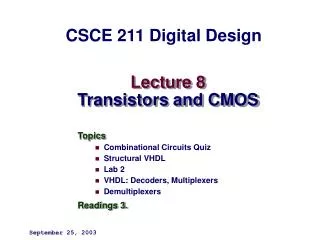
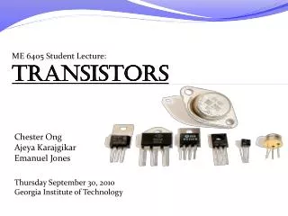
SEMICONDUCTORS LECTURE 16 TRANSISTORS. TRANSISTORS P.48. LECTURE#16. First commercial transistor. First transistor 1947. First computer to use these transistors. BIPOLAR TRANSISTORS ARE SEMICONDUCTOR DEVICES WITH 3 LEADS, CALLED THE EMITTER, BASE AND COLLECTOR. THE TRANSISTOR IS

E N D
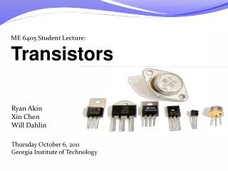
TRANSISTORS P.48 LECTURE#16 First commercial transistor First transistor 1947
BIPOLAR TRANSISTORS ARE SEMICONDUCTOR DEVICES WITH 3 LEADS, CALLED THE EMITTER, BASE AND COLLECTOR. THE TRANSISTOR IS BASICALLY 2 P-N JUNCTIONS BUTTED UP AGAINST EACH OTHER. A SMALL VOTLAGE OR CURRENT AT ONE LEAD CAN CONTROL A MUCH LARGER VOLTAGE OR CURRENT AT THE OTHER TWO. TRNSISITORS CAN BE USED AS AMPLIFERS OR AS SWITCHES. ACTS LIKE A 3 LAYER SANDWICH YOU TUBE: HOW TRANSISTORS WORK http://www.youtube.com/watch?v=ZaBLiciesOU
THIS LAYERING CAN BE PNP OR NPN THE MIDDLE LAYER (BASE) CAN ACT AS A GATE CONTROLING THE CURRENT THRU THE 3 LAYERS. THE BASE LAYER IS THIN AND HAS LESS DOPING ATOMS THEN THE EMITTER AND COLLECTOR. A SMALL BASE CURRENT WILL CAUSE A LARGER EMITTER-COLLECTOR CURRENT TO FLOW.
INPORTANT POINTS TO REMENBER ABOUT TRANSISTOR OPERATION. 1. THE BASE-EMITTER JUNCTION WILL NOT CONDUCT UNTIL THE FORWARD VOLTAGE EXCEEDS 0.6VDC 2. TOO MUCH HEAT CAN DESTROY OR CAUSE A TRANSISTOR NOT TO OPERATE CORRECTLY. 3. TOO MUCH VOLTAGE OR CURRENT WILL DESTROY THE CHIP INSIDE THE TRANSISTOR OR CAUSE THE LEADS ATTACHED TO IT TO MELT. How the first transistor worked http://www.youtube.com/watch?v=RdYHljZi7ys
YOU TUBE: MAKE PRESENTS THE TRANSISTOR http://www.youtube.com/watch?v=-td7YT-Pums
WHEN THE BASE IS GROUNDED (0V) NO CURRENT FLOWS FROM THE EMITTER TO THE COLLECTOR. IF ABOUT 0.6V IS APPILED TO THE BASE THE TRANSISTOR IS SAID TO BE FOWARD BAISED, CURRENT WILL FLOW FROM THE EMITTER TO THE COLLECTOR (TRANSISTOR IS ON). TRANSISTOR IS OPERATING AS A SWITCH. How to use transistor as switch.mp4 http://www.youtube.com/watch?v=HTQQnl1pArk
CALLED COMMON EMITTER CIRCUIT SINCE BOTH EMITTERS ARE GROUNDED
2N3055 TO-3 OPENED 2N3055 IS COMMONLY USED IN POWER SUPPLIES
YOU TUBE: Field Effect Transistors, Part 1,START AT 7:00MIN http://www.youtube.com/watch?v=CLLcRRBph90
JFET Channel Pinched-off Bias arrangement for an N-channel JFET
MOSFETS: METAL OXIDE SEMICONDUCTORS-FETS MOSFETS ARE USED IN MICROPROCESSORS AND MEMORY CIRUITS DUE TO THEIR EASE OF MANUFACTURE, SMALL SIZE, LOW POWER USE, AND HIGH OPERATING SPEED. SUBJECT TO ESD DAMAGE. GENERALLY CAN’T HANDLE HIGH POWER LEVELS n-channel metal-oxide semiconductor
The MOSFET http://www.youtube.com/watch?NR=1&feature=endscreen&v=x7OnX6e5pvc How a CMOS Chip Works (digital camera) http://www.youtube.com/watch?v=HEVEGVV4EHk
(ACTS AS AN INSULATOR) GATE HAS NO ELECTRICAL CONTACT BETWEEN THE SOURCE AND THE GATE YOU TUBE: transistor/mosfet tutorial Exploding electronic components in HD http://www.youtube.com/watch?v=Te5YYVZiOKs http://www.youtube.com/watch?v=JCPXckfT-6g
ESD PRECAUTONS YOU TUBE: ESD PREVENTION MEASURES http://www.youtube.com/watch?v=QNahnyx9OWQ
Thyristor with voltage Range from 400 to 1kv Current 16A to600A 2 gates Cathode Anode
DIFFERENT PACKAGE CASES FOR THYRISTORS CCEA AS Technology and Design Unit1 - The Thyristor http://www.youtube.com/watch?v=TFuiqDbkAX0
This circuit detects light when light is present in a room. With no light, the photo-transistor does not conduct. When light is present, the photo-transistor conducts and the bell is activated. Turning off the light will not stop the alarm. The alarm is turned off via S1. Alarm device using a thyristor and a photo-transistor Animation of SCR Operation
SCR / Thyristor module, 6500V, 1,500A for 50us pulse (hockey puck)
A diac is a diode AC switch which acts as a bidirectional semiconductor switch. TRIAC IS THE SAME AS 2 REVERSE PARALLEL SCR’s
A diac is a full-wave or bi-directional semiconductor switch that can be turned on in both forward and reverse polarities. Indeed the name diac means diode AC switch.
Symbols and pin placements for: a - thyristor, b - triac, c - diac THYRISTORS DIACS K: Cathode TRIACS
The diac is widely used to assist even triggering of a triac when used in AC switches. Diacs are mainly used in dimmer applications and also in starter circuits for florescent lamps. TRIACs are like 2 parallel SCRsThey are thus able to switch both sides of an AC sine waveThey are often switched using DIACSThey can be used to control AC loads by switch action or the progressive trimming of the sine wave Through the use of optical coupling they can be safely interfaced with computer control circuits!
A pushbutton switch controls the flow of current in a load HOW AC DIMMER SWITCHES WORK Current injected into the GATE controls the TRIAC A TRIAC switch controls the current through a loadBecause it can be controlled to trigger at different voltage points on the sine wave it can be used to effectively control the RMS power delivered to the load rather just crude on / off.It's like a switch that can turn on and off at different times on the sine wave.
The TRIAC is a gate controlled switch. Low voltage logic circuits are fragile and expensive they should be electrically isolated from the high voltage TRIAC circuit using an Optocoupler module chip
RMS power and voltage to the load are controlled by trimming of the AC sine wave.