Download
1 / 23
240 likes | 539 Vues
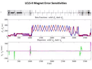
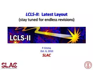
The LCLS-II BSY , LTU, and UH Layout. Paul Emma et al. May 18, 2011 LCLS-II Meeting. LCLS-II Machine Layout. New injector at sector-10 (1 km upstream) Two new bunch compressors and 4-14 GeV linac (~1 km) 1200-m long bypass (old PEP-II 9-GeV line) goes around LCLS-I. RF gun-2. RF

E N D
The LCLS-II BSY, LTU, and UH Layout Paul Emma et al. May 18, 2011 LCLS-II Meeting
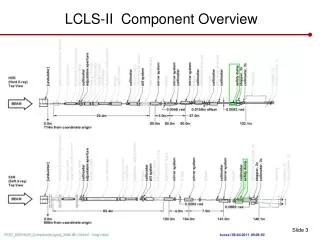
LCLS-II Machine Layout • New injector at sector-10 (1 km upstream) • Two new bunch compressors and 4-14 GeVlinac (~1 km) • 1200-m long bypass (old PEP-II 9-GeV line) goes around LCLS-I RF gun-2 RF gun-1 LCLS-II LCLS-I existing L0 L0 und-hall-1 LCLS-I X X L1 BC1 L2 BC2 L3 L1 BC1 L2 BC2 L3 3-15 GeV one more km of linac Sector-20 wall HXR 4-14 GeV bypass line SXR und-hall-2
Inside Linac Tunnel - Looking Downstream Use existing PEP-II bypass line on linac tunnel ceiling (FODO cells with one quad every 101.6 m) Moves LCLS-II 25.57” higher than LCLS-I 9-GeV (PEP-II) 25.610” 17” 3-GeV (PEP-II) 25.570” 120” LINAC 47” 66” (ID-344-013-30) 132” DOE CD-1 Review of the LCLS-II Project, April 26-28, 2011
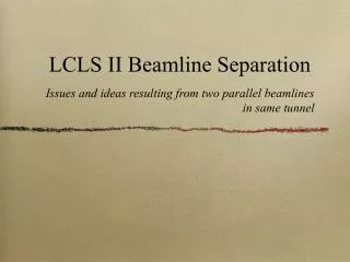
Existing Bypass Line in Linac Tunnel LCLS-II Bypass Line
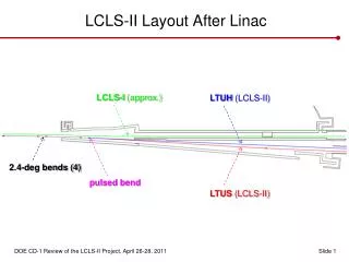
LCLS-II Layout After Linac LCLS-I (approx.) LTUH (LCLS-II) 2.4-deg bends (4) pulsed bend LTUS (LCLS-II) Armin Busse
LCLS-II Layout After Linac Need 2 low-profile quads here Pulsed bend
Head-House Port (South Side) LCLS-II-H LCLS-II-S 2.67 m LCLS-I X’ = -1.25 m Y’ = -0.90 m 0.51 m 3.05 m (10.0 ft) 2.05 m 1.01 m (3.30 ft) 2.43 m (7.97 ft) 2.12 m (6.96 ft) 0.92 m (3.02 ft) Wall face at Z’(LCLS) = 346.24 m
LCLS-II Line Fits Close to LCLS-I in BTH LCLS-II LCLS-I DOE CD-1 Review of the LCLS-II Project, April 26-28, 2011
LCLS-II Beam Transport Layout Undulator Hall, LCLS-I e- dump LTU1 FEE1 LCLS-I LINAC HXR Exp. Hall pulsed dipole 2.4° New Undulator Hall, LCLS-2 LTUH SXR LTU2 e- dump-H FEEH 2.5 m LTUS e- dump-S FEES
Start-2-End Tracking with LCLS-II Optics bypass line 2.4° bends BC1 BC2 HXR und. SXR not shown Thanks to M. Woodley and Y. Nosochkov
LCLS-II Electron Beam Diagnostics YAG screens OTR screens Wire scanners Bunch length mon. gun sd sd sd sd L0 µ 11-1 sd sz sd L1 L3 L2 sz sz BC1 BC2 11-3 to 14-4 DL1 sd 14-7 to 20-4 DL2 HXR SXR sd • 2 Transverse RF cavities (135 MeV & 5 GeV) • 6 YAG screens • 8 OTR screens • 19 wire scanners (each with x & y wires) • 3 bunch length monitors • Gun spectrometer, injector spectrometer, dump spectrometer • BC1 stopper, abort kicker, BSY stopper, 2 undulator stoppers
Muon Plug Wall Exit to HXR Dump HXR Emittance Diagnostics and Collimation Self-Seeding Section H-Dump Vert. bends 2.4-deg bends HXR matching m-plug HXU Y. Nosochkov
New Abort Kicker Located Above Old D10 Box A. Ibrahimov
New D2’ Stopper Needed (B-Line Bends Get Removed) A. Ibrahimov
New D2’ Stopper in BSY (and its backup stoppers) m-plug wall QA0 ST61 QBP34 ST61’ ST60’ D2’ A. Ibrahimov
Start of Muon Plug Wall (17 m thick iron) A. Ibrahimov
HXR Matching Section, HXU, and Dump H-Dump HXR Self-Seeding Section HXR Matching HXU Y. Nosochkov
Muon Plug Wall Exit to SXR Dump septum SXR Emittance Diagnostics and Collimation Self-Seeding Section S-Dump Vert. bends SXR matching 2.4-deg bends m-plug SXU Y. Nosochkov
SXR 3-WireEmittance Diagnostics Section + Collimation WSLTUS1 WSLTUS3 WSLTUS2 Dx,y = 90 Dx,y = 120 SXR Emittance Diagnostics and Collimation Y. Nosochkov
SXR Matching Section, SXU, and Dump S-Dump Self-Seeding Section SXR matching SXU Y. Nosochkov
New Features in LCLS-II • Y-kicker + HLAM magnets in BTH to split beam into HXR & SXR @ 60 Hz each • LTUH line has 4 LTU-like wire-scanners and 2/2 final x/y collimators • LTUS line has 3 BC1-like wire-scanners and 2/2 final x/y collimators • Each undulator line has an insertable stopper (TDUNDH & TDUNDS) • Future self-seeding sections leads each new undulator (30-100 m) • Two separate electron beam dumps • Soft bends start each dump bend (no Be foil needed) • Two separate x-ray front-ends (diagnostics – J. Welch, P. Heimann, J. Frisch)