Download
1 / 23
230 likes | 335 Vues
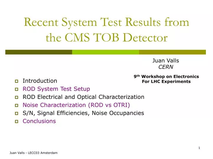
Recent System Test Results from the CMS TOB Detector. Juan Valls CERN. 9 th Workshop on Electronics For LHC Experiments. Introduction ROD System Test Setup ROD Electrical and Optical Characterization Noise Characterization (ROD vs OTRI) S/N, Signal Efficiencies, Noise Occupancies

E N D
Recent System Test Results from the CMS TOB Detector Juan Valls CERN 9th Workshop on Electronics For LHC Experiments • Introduction • ROD System Test Setup • ROD Electrical and Optical Characterization • Noise Characterization (ROD vs OTRI) • S/N, Signal Efficiencies, Noise Occupancies • Conclusions Juan Valls - LECC03 Amsterdam
Introduction • CMS SST • Total of ~25000 Si modules in Barrel (10 layers) and Endcap (18 disks) • 80000 FE chips, 50000 optical links • TOB: 6 layers (~5000 silicon modules) • 10-14 points per track • 223 m2 of silicon (CDF ~2 m2, ATLAS ~60 m2 ) • 10M of readout strips T=-10 oC RODs: basic TOB readout units (~700 RODs) ~25 m3 Juan Valls - LECC03 Amsterdam
CCUM 7 9 11 1 3 5 2 4 6 8 10 12 RODs Assembly • 6 (SS) or 12 (DS) silicon modules • Interconnection electronics (ICB, ICC) • Control electronics (CCUM) • Optoelectronics (AOH) • Cooling pipe + module cooling elements ICCs ICB CF frame profile Juan Valls - LECC03 Amsterdam
ROD Assembly (Readout) 24 fibers Analog Optohybrids (AOH ICs) Juan Valls - LECC03 Amsterdam
ROD System Test Setup Optical Readout (~3 m) HV LV C6F14 Cooling Plant FEC2CCUM board TOB DS ROD Layer 1 Electrical Controls 1 kW +5C/+32C Juan Valls - LECC03 Amsterdam
Thermal Behavior LV off LV on LV off T (Si-pipe) 6 °C T (°C) Design figure: DT < 10 °C with irradiated sensors and highest optohybrid settings • All tests at room temp • To be repeated in the cold t (sec) DS ROD SS ROD Juan Valls - LECC03 Amsterdam
System Tests Main objectives of pre-production phase (system tests) are the validation of the overall design structure before production • Integrate sensors with FE electronics, interconnecting boards and buses in the final mechanical support • Integrate full optical link for signal distribution (control and readout) • Integrate HV and LV power, long cables and test LV power uniformity • Verify electrical tests to check integrity of signals (timing and control) through transmission between cards • Tunning of the controls and analogue optical links • Validate grounding and detector bias schemes by studying noise • Analysis of data from sensors, S/N ratios, signal efficiencies and strip noise occupancies Juan Valls - LECC03 Amsterdam
Analogue Readout 40000 links @ 40MS/s FED Detector Hybrid A-Opto Hybrid 96 Rx Module processing MUX A buffering 12 APV 3 DAQ 2:1 D amplifiers 12 C pipelines 128:1 MUX PLL Delay PLL DCU TTCRx TTC Digital Control 2500 links @40MHz FEC Control D-Opto Hybrid TRx Module 64/96 4 TTCRx CCU CCU 8/12 processing buffering CCU CCU Back-End Front-End Control and Readout Front End Drivers Front End Controllers Juan Valls - LECC03 Amsterdam
Time Alignment Scans • Scan through PLL fine delays (1.04 ns) and with a fixed FED digitization delay • Reconstruct APV tick marks • The DS ROD introduces shift delays of ~2 ns on the trigger arrival time to APVs. FED 0 FED 1 FED 2 Juan Valls - LECC03 Amsterdam
FED Digitizing Point • Find the FED optimal digitization point • Reconstruct APV tick marks by varying FED skew clock delay wrt data (PLL settings fixed) • Choose sampling point close to the back edge of the tick mark FED 0 FED 1 FED 2 Juan Valls - LECC03 Amsterdam
Optical Scan Characterization • Plot ticks and baselines as a function of bias (for a fixed gain) • Get the tick amplitude from the difference between these distributions AOH Gain = 1 (24 fibers) baselines tick amplitudes ticks AOH bias AOH bias Juan Valls - LECC03 Amsterdam
Gain 0 Gain 1 Gain 2 150-210 counts Gain 0 Gain 1 Gain 2 Bias Optical Scan Characterization • Find optimal settings (gain and bias) for an 800 mV AOH input tick amplitude • What does this correspond to at the FED (in ADC counts)? • Need to calibrate FED cards: FED gain ~3.5 mV/count, Optolink gain ~0.8V/V Juan Valls - LECC03 Amsterdam
DS ROD Noise Deconvolution Non-Inverting (200 V) tot diff CMN CCUM Juan Valls - LECC03 Amsterdam
DS ROD CMN CMN (flat) Calculation (running average pedestals) Non-Inverting Inverting ~40% Juan Valls - LECC03 Amsterdam
DS ROD HV Scans HV Bias Scan on DS ROD 6 HV channels for 12 modules (CAEN SY-127, A343 boards) Total noise (ADC) = f (Vbias) Full depletion at ~150 Volts Similar behavior for all modules 30% larger Noise in the DS ROD wrt OTRI setup Juan Valls - LECC03 Amsterdam
OTRI • ROD Peak Mode Non-Inverting • ROD • OTRI Deconvolution Non-Inverting Full Gain Scans Ical=29 ~ 25000 elec Fit Range: Ical=18 to Ical=70 0.6 – 2.7 MIPs ~ 850 e/ADC (OTRI) ~ 650 e/ADC (ROD) Juan Valls - LECC03 Amsterdam
Noise (DS ROD vs OTRI) OTRI Setup Peak: 1600 elec. Dec: 2600 elec. Peak Mode Non-Inverting DS ROD Setup Peak: 1600 elec. Dec: 2700 elec. APV25 bare chip on PCB (Cinp=18 pF) Peak: 900 elec. Dec: 1500 elec. Deconvolution Non-Inverting Juan Valls - LECC03 Amsterdam
S/N S/N>5 ~500 Hz ~0.5 Hz S/N>2 Signal to Noise Ratios • Use Ru106 beta source and cosmic rays • Simple cluster algorithm based on S/N thresholds S/N=14.1 S/N=14.9 S/N=23.2 S/N=25.9 S/N=14.7 S/N=15.3 Juan Valls - LECC03 Amsterdam
Efficiencies, Strip Occupancies • The FEDs will run a cluster finding algorithm (zero-suppression) during data taking • Only strips associated with clusters will be readout (LVL1 100 kHz Occupancies < 1.8%) Signal Efficiencies Strip Occupancies Juan Valls - LECC03 Amsterdam
Signal Efficiencies vs Noise Occupancies 2 (2.3%) = 100% 3 (0.14%) = 99.7% 4 (0.003%) = 96.4% 2 (2.3%) = 100% 3 (0.14%) = 98% 4 (0.003%) = 94.5% Juan Valls - LECC03 Amsterdam
Conclusions • Mechanical and electrical performance of pre-production RODs validated in system tests and test-beams at CERN • Thermal behavior and cooling performance verified at room temperature • Electrical tests verified • Grounding and detector bias schemes validated • S/N studied • On the way to production… • First production ROD assembled and characterized at CERN last week • Production started • ~760 RODs to be assembled at CERN and USA Juan Valls - LECC03 Amsterdam
XROD Software Frames • ROD FAST debugging tool • CMS-like DAQ hardware • Access to BE boards • TSC, FEC, FED, CCUM • Handles CCU6 and CCU25 • Access to FE registers • PLL, MUX, APV, DCU, AOH • Handles DCU1 and DCU2 • Handles LLD1 and LLD2 • Internal/external TSC triggers (and FED internal) • Single GUI Interface Noise Gain Scan Pulse Shape Scan Juan Valls - LECC03 Amsterdam
Module Biasing Scheme TOB / TEC TIB Vbias NAIS HV Connector on Kapton Cable GND Bias Connector on Kapton Cable GND (wirebond to bias ring) Vbias Juan Valls - LECC03 Amsterdam