Download
1 / 20
220 likes | 366 Vues
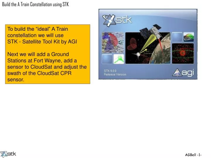
To build the “ideal” A Train constellation we will use STK - Satellite Tool Kit by AGI Next we will add a Ground Stations at Fort Wayne, add a sensor to CloudSat and adjust the swath of the CloudSat CPR sensor. Lets add Fort Wayne to our

E N D
To build the “ideal” A Train constellation we will use STK - Satellite Tool Kit by AGI Next we will add a Ground Stations at Fort Wayne, add a sensor to CloudSat and adjust the swath of the CloudSat CPR sensor.
Lets add Fort Wayne to our A Train scenario. Select Insert>Facility From City Database.
Type in and search for Fort Wayne and then select insert.
How about if we wanted to determine when the satellites can communicate with the Fort Wayne ground station? Select Access
Select all the satellites and then hit the “Compute” button.
When the satellite can communicate to the Fort Wayne ground station a line appears between the satellite and Fort Wayne
Let remove all the reference grids and vectors and add the CPR instrument to CloudSat
To add an instrument select Insert>Object Catalog The Object Catalog form will pop-up and select “Sensor”
The new sensor “footprint” or swath defaults to a Simple Conic, 45 degrees.
CloudSat’s CPR actually has a rectangular swath. CloudSat swath 1. 4 km by 2.5 km
The swath dimensions must be translated into angles. (eq 2) (eq 1) (eq 3) Use equation 1 to determine Based on how big you want your “swath” to be Use equation 2 to determine Use equation 3 to determine Two “nadir angles” entered into STK for Vertical and Horizontal Half Angles embedded spreadsheet http://www.smad.com/store/bookstore/stl/smad3err.pdf
STK has some additional information of creating a rectangular sensor pattern in the STK help area.
Entered the full angles not the half angles. It should get a swath that is twice as wide and twice as long?
Width is 1.4 km? Using this tool measure the width and length of the swath.
Length is 2.5 km? Swath size is 1.4 by 2.5 for the angles entered. Conclusion, if you use the spreadsheet “nadir angles” you do not need to divide by two.
6 ft 1/8 inch 0.5 miles By comparison using the calculated swath size (1.4 km) divided by the CloudSat altitude (705 km), a six foot man looks like 1/8 inch tall from a half a mile awayand would be hard to see. Therefore, we will scale the size of the swath. We will scale the swath width and length by 50 times so we can see it better. We will make the swath 2.84° by 5.07°
With the Vertical Half Angle to 2.84°and the Horizontal Half Angle to 5.07°. Actually, is will make our swath area 2500X larger than the actual swath size for CloudSat’s CPR.
Click to see measurement of the swath size Swath area increased by 2500X times or 8,740 km2 Click on the picture to see the scenario.