Download
1 / 66
660 likes | 677 Vues
ECE 448 Lecture 7. VGA Display Part 1. Required R eading. P. Chu, FPGA Prototyping by VHDL Examples Chapter 12, VGA Controller I: Graphic Source Codes of Examples http://academic.csuohio.edu/chu_p/rtl/fpga_vhdl.html Nexys3 Reference Manual VGA Port, pages 15-17. Basics.

E N D
ECE 448 Lecture 7 VGA DisplayPart 1 ECE 448 – FPGA and ASIC Design with VHDL
Required Reading • P. Chu, FPGA Prototyping by VHDL Examples • Chapter 12, VGA Controller I: Graphic • Source Codes of Examples • http://academic.csuohio.edu/chu_p/rtl/fpga_vhdl.html • Nexys3 Reference Manual • VGA Port, pages 15-17 ECE 448 – FPGA and ASIC Design with VHDL
Basics ECE 448 – FPGA and ASIC Design with VHDL
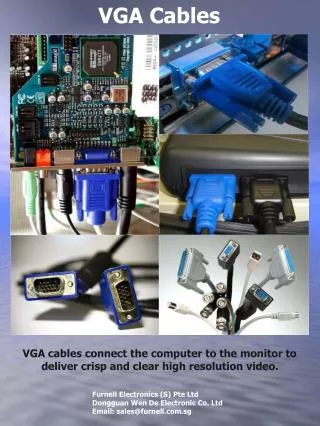
VGA – Video Graphics Array • Video display standard introduced in the late 1980’s • Widely supported by PC graphics hardware • and monitors • Used initially with the CRT (cathode ray tube) • monitors • Later adopted for LCD monitors as well ECE 448 – FPGA and ASIC Design with VHDL
VGA – Characteristic Features • Resolution: 640x480 • Display: up to 256 colors (8 bits) • Refresh Rate: 25Hz, 30Hz, 60Hz (frames / second) • RGB: Red, Green and Blue analog signals ECE 448 – FPGA and ASIC Design with VHDL
Operation of a CRT monitor ECE 448 – FPGA and ASIC Design with VHDL
CRT Monitor – Conceptual Diagram ECE 448 – FPGA and ASIC Design with VHDL
CRT Monitor – Scanning Pattern ECE 448 – FPGA and ASIC Design with VHDL
CRT Monitor – Horizontal Scan ECE 448 – FPGA and ASIC Design with VHDL
VGA Controller ECE 448 – FPGA and ASIC Design with VHDL
VGA Controller – Simplified View ECE 448 – FPGA and ASIC Design with VHDL
Three-bit VGA Color Combinations ECE 448 – FPGA and ASIC Design with VHDL
VGA Synchronization ECE 448 – FPGA and ASIC Design with VHDL
Horizontal Synchronization ECE 448 – FPGA and ASIC Design with VHDL
Four regions of hsync • Display: 0..639, width = 640 • Right border (front porch): 640..655, width = 16 • Retrace (horizontal flyback): 656..751, width=96 • Left border (back porch): 752..799, width=48 ECE 448 – FPGA and ASIC Design with VHDL
Vertical Synchronization ECE 448 – FPGA and ASIC Design with VHDL
Four regions of vsync • Display: 0..479, width = 480 lines • Bottom border (front porch): 480..489, width = 10 • Retrace (vertical flyback): 490..491, width=2 • Top border (back porch): 491..524, width=33 ECE 448 – FPGA and ASIC Design with VHDL
Pixel Rate • p: the number of pixels in a horizontal scan line • p = 800 pixels/line • l: the number of horizontal lines in a screen • l = 525 lines/screen • s: the number of screens per second (refresh rate) • s = 60 screens/second Pixel Rate = p l s = 25 Mpixels/second ECE 448 – FPGA and ASIC Design with VHDL
VHDL Code of VGA Sync ECE 448 – FPGA and ASIC Design with VHDL
Assumptions • 50 MHz clock • => 2 clock cycles per pixel • => p_tick generated every second clock period • used as an enable for the horizontal counter ECE 448 – FPGA and ASIC Design with VHDL
VHDL Code of VGA Sync (1) library ieee; use ieee.std_logic_1164.all; use ieee.numeric_std.all; entity vga_sync is port( clk, reset: in std_logic; hsync, vsync: out std_logic; video_on, p_tick: out std_logic; pixel_x, pixel_y: out std_logic_vector (9 downto 0) ); end vga_sync; ECE 448 – FPGA and ASIC Design with VHDL
VHDL Code of VGA Sync (2) architecture arch of vga_sync is -- VGA 640-by-480 sync parameters constant HD: integer:=640; --horizontal display area constant HF: integer:=16 ; --h. front porch constant HR: integer:=96 ; --h. retrace constant HB: integer:=48 ; --h. back porch constant VD: integer:=480; --vertical display area constant VF: integer:=10; --v. front porch constant VR: integer:=2; --v. retrace constant VB: integer:=33; --v. back porch ECE 448 – FPGA and ASIC Design with VHDL
VHDL Code of VGA Sync (3) -- mod-2 counter signal mod2_reg, mod2_next: std_logic; -- sync counters signal v_count_reg, v_count_next: unsigned(9 downto 0); signal h_count_reg, h_count_next: unsigned(9 downto 0); -- output buffer signal v_sync_reg, h_sync_reg: std_logic; signal v_sync_next, h_sync_next: std_logic; -- status signal signal h_end, v_end, pixel_tick: std_logic; ECE 448 – FPGA and ASIC Design with VHDL
VHDL Code of VGA Sync (4) process (clk, reset) begin if reset='1' then mod2_reg <= '0'; v_count_reg <= (others=>'0'); h_count_reg <= (others=>'0'); v_sync_reg <= '0'; h_sync_reg <= '0'; elsif (clk'event and clk='1') then mod2_reg <= mod2_next; v_count_reg <= v_count_next; h_count_reg <= h_count_next; v_sync_reg <= v_sync_next; h_sync_reg <= h_sync_next; end if; end process; ECE 448 – FPGA and ASIC Design with VHDL
VHDL Code of VGA Sync (5) -- mod-2 circuit to generate 25 MHz enable tick mod2_next <= not mod2_reg; -- 25 MHz pixel tick pixel_tick <= '1' when mod2_reg='1' else '0'; -- status h_end <= -- end of horizontal counter '1' when h_count_reg=(HD+HF+HR+HB-1) else --799 '0'; v_end <= -- end of vertical counter '1' when v_count_reg=(VD+VF+VR+VB-1) else --524 '0'; ECE 448 – FPGA and ASIC Design with VHDL
VHDL Code of VGA Sync (6) -- mod-800 horizontal sync counter process (h_count_reg, h_end, pixel_tick) begin if pixel_tick='1' then -- 25 MHz tick if h_end='1' then h_count_next <= (others=>'0'); else h_count_next <= h_count_reg + 1; end if; else h_count_next <= h_count_reg; end if; end process; ECE 448 – FPGA and ASIC Design with VHDL
VHDL Code of VGA Sync (7) -- mod-525 vertical sync counter process (v_count_reg, h_end, v_end, pixel_tick) begin if pixel_tick='1' and h_end='1' then if (v_end='1') then v_count_next <= (others=>'0'); else v_count_next <= v_count_reg + 1; end if; else v_count_next <= v_count_reg; end if; end process; ECE 448 – FPGA and ASIC Design with VHDL
VHDL Code of VGA Sync (8) -- horizontal and vertical sync, buffered to avoid glitch h_sync_next <= ‘0' when (h_count_reg >= (HD+HF)) --656 and (h_count_reg <= (HD+HF+HR-1)) else --751 ‘1'; v_sync_next <= ‘0' when (v_count_reg >= (VD+VF)) --490 and (v_count_reg <= (VD+VF+VR-1)) else --491 ‘1'; -- video on/off video_on <= '1' when (h_count_reg<HD) and (v_count_reg<VD) else '0'; ECE 448 – FPGA and ASIC Design with VHDL
VHDL Code of VGA Sync (9) -- output signal hsync <= h_sync_reg; vsync <= v_sync_reg; pixel_x <= std_logic_vector(h_count_reg); pixel_y <= std_logic_vector(v_count_reg); p_tick <= pixel_tick; end arch; ECE 448 – FPGA and ASIC Design with VHDL
VGA Sync Testing Circuit (1) library ieee; use ieee.std_logic_1164.all; entity vga_test is port ( clk, reset: in std_logic; sw: in std_logic_vector(2 downto 0); hsync, vsync: out std_logic; rgb: out std_logic_vector(2 downto 0) ); end vga_test; architecture arch of vga_test is signal rgb_reg: std_logic_vector(2 downto 0); signal video_on: std_logic; ECE 448 – FPGA and ASIC Design with VHDL
VGA Sync Testing Circuit (2) begin vga_sync_unit: entity work.vga_sync port map(clk=>clk, reset=>reset, hsync=>hsync, vsync=>vsync, video_on=>video_on, p_tick=>open, pixel_x=>open, pixel_y=>open); process (clk, reset) begin if reset='1' then rgb_reg <= (others=>'0'); elsif (clk'event and clk='1') then rgb_reg <= sw; end if; end process; rgb <= rgb_reg when video_on='1' else "000"; end arch; ECE 448 – FPGA and ASIC Design with VHDL
Pixel Generation Circuit ECE 448 – FPGA and ASIC Design with VHDL
VGA Controller – Simplified View ECE 448 – FPGA and ASIC Design with VHDL
Bit-Mapped Pixel Generation Circuit • Video memory is used to store data to be displayed • on the screen • Each pixel is represented by a memory word • holding its color • Graphics processing circuit continuously updates • the screen by writing to the video memory, • which is then read by the Pixel Generation Circuit • Memory needed • 640480 = 310 kbits for a monochrome display • 6404803 = 930 kbits for an 8-color display ECE 448 – FPGA and ASIC Design with VHDL
Tile-Mapped Pixel Generation Circuit • Tile = a group of pixels, e.g., 8x8 square of pixels • The 640x480 pixel-oriented screen becomes • an 80x60 tile-oriented screen • The tile can hold a limited number of patterns, e.g. 32 • For each tile we need to store the number • of a displayed pattern (in the range 0..31) • Tile memory • 8060 tiles/screen 5 bits/tile ≈ 24 kbits • Pattern memory • 32 patterns 64 bits/pattern = 2kbit ECE 448 – FPGA and ASIC Design with VHDL
Example of a Tile Pattern ECE 448 – FPGA and ASIC Design with VHDL
Object-Mapped Scheme • RGB signals are generated on the fly based • on the values of x and y coordinates • (pixel_x, pixel_y) • Applicable to a limited number of simple objects • No memory needed ECE 448 – FPGA and ASIC Design with VHDL
Graphic Generation with an Object Mapped Scheme ECE 448 – FPGA and ASIC Design with VHDL
Object-Mapped Pixel Generation ECE 448 – FPGA and ASIC Design with VHDL
Still Screen of the Pong Game ECE 448 – FPGA and ASIC Design with VHDL
Generation of the Wall Stripe 32 ≤ x ≤ 35 ECE 448 – FPGA and ASIC Design with VHDL
Generation of the Wall Stripe in VHDL -- wall left, right boundary constant WALL_X_L: integer:=32; constant WALL_X_R: integer:=35; ….. -- pixel within wall wall_on <= '1' when (WALL_X_L<=pix_x) and (pix_x<=WALL_X_R) else '0'; -- wall rgb output wall_rgb <= "001"; -- blue ECE 448 – FPGA and ASIC Design with VHDL
Generation of the Bar (Paddle) 600 ≤ x ≤ 603 204 ≤ y ≤ 275 ECE 448 – FPGA and ASIC Design with VHDL
Generation of the Bar in VHDL constant MAX_X: integer:=640; constant MAX_Y: integer:=480; constant BAR_X_L: integer:=600; constant BAR_X_R: integer:=603; constant BAR_Y_SIZE: integer:=72; constant BAR_Y_T: integer:=MAX_Y/2-BAR_Y_SIZE/2; --204 constant BAR_Y_B: integer:=BAR_Y_T+BAR_Y_SIZE-1; ….. bar_on <= '1' when (BAR_X_L<=pix_x) and (pix_x<=BAR_X_R) and (BAR_Y_T<=pix_y) and (pix_y<=BAR_Y_B) else '0'; bar_rgb <= "010"; --green ECE 448 – FPGA and ASIC Design with VHDL
Generation of the Square Ball 580 ≤ x ≤ 587 238 ≤ y ≤ 245 ECE 448 – FPGA and ASIC Design with VHDL
Generation of the Square Ball in VHDL constant BALL_SIZE: integer:=8; constant BALL_X_L: integer:=580; constant BALL_X_R: integer:=BALL_X_L+BALL_SIZE-1; constant BALL_Y_T: integer:=238; constant BALL_Y_B: integer:=BALL_Y_T+BALL_SIZE-1; ….. sq_ball_on <= '1' when (BALL_X_L<=pix_x) and (pix_x<=BALL_X_R) and (BALL_Y_T<=pix_y) and (pix_y<=BALL_Y_B) else '0'; ball_rgb <= "100"; -- red ECE 448 – FPGA and ASIC Design with VHDL
Selection and Multiplexing Circuit ECE 448 – FPGA and ASIC Design with VHDL
Selection and Multiplexing in VHDL process(video_on, wall_on, bar_on, sq_ball_on, wall_rgb, bar_rgb, ball_rgb) begin if video_on='0' then graph_rgb <= "000"; --blank else if wall_on='1' then graph_rgb <= wall_rgb; elsif bar_on='1' then graph_rgb <= bar_rgb; elsif sq_ball_on='1' then graph_rgb <= ball_rgb; else graph_rgb <= "110"; -- yellow background end if; end if; end process; ECE 448 – FPGA and ASIC Design with VHDL
Pixel Generation Circuit for the Pong Game Screen ECE 448 – FPGA and ASIC Design with VHDL
VHDL Code of Pixel Generation (1) library ieee; use ieee.std_logic_1164.all; use ieee.numeric_std.all; entity pong_graph_st is port( video_on: in std_logic; pixel_x, pixel_y: in std_logic_vector(9 downto 0); graph_rgb: out std_logic_vector(2 downto 0) ); end pong_graph_st; ECE 448 – FPGA and ASIC Design with VHDL