Download
1 / 36
360 likes | 425 Vues
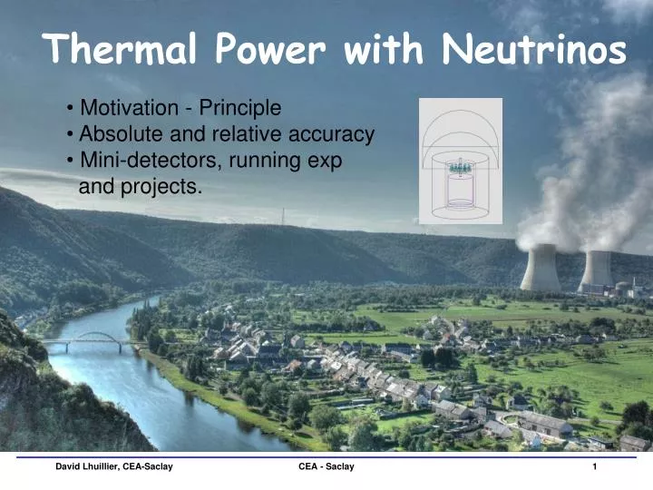
Thermal Power with Neutrinos. Motivation - Principle Absolute and relative accuracy Mini-detectors, running exp and projects. Motivations. Standard power measurements:

E N D
Thermal Power with Neutrinos • Motivation - Principle • Absolute and relative accuracy • Mini-detectors, running exp • and projects. CEA - Saclay
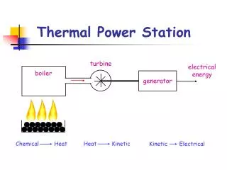
Motivations • Standard power measurements: • n counters: very large dynamic, high sensitivity to relative changes. But flux distortions lead to complex translation into Pth number. • Heat evacuated by coolant: depends on flow profile and turbulences. • Pth/Pth? Getting an argued answer turns out to be a challenge (or maybe Michel didn’t try hard enough, he contacted only 12 potential speakers)... • Neutrino approach: • very complementary, mostly independent syst errors. • Interest for absolute measurement and low frequency remote monitoring using simple and low cost detectors. • Prototype of ~1m3mini-detector to establish achievable precision. CEA - Saclay
Z Z=N Fission products evolve toward stability via decay chains 235U N 56 36 92 Sr 92 Rb 38 37 e e (no threshold) Leading Order Approach Fission of 235U CEA - Saclay
Leading Order Approach • ocsillate: P(ee) = P(E,L) But no significant flux distortion with E= few MeV and L = few 10m Kamland, PRL 90 (2003) 021802 • Sensitive to weak interaction only, almost no int. with matter≤10-17 barn Reactor core spectrum flux = direct image of Pth CEA - Saclay
e Detection e + p e+ + n inverse process: Prompt e+ signal Eprompt = E-Mn-Mp+me & Threshold: Mn -Mp + Me = 1.8 MeV Delayed n capture after thermalization CEA - Saclay
int. rate Flux 1.8 MeV threshold e Detection Huge flux compensate tiny cross section. Miniature detector very close to reactor core can reach pretty high counting rate: ( det = 50%) 1t target @ 25m of 1GWe reactor 1% stat on total flux within 5.5 days CEA - Saclay
Going to NLO Fuel burn-up: CEA - Saclay
235U 239Pu A Fissile Isotopes spectra Fission fragments from 239Pu heavier in the light hump corresponding energy spectra are different CEA - Saclay
All curves normalized to same number of fissions Fissile Isotopes spectra For a constant Pth, the of neutrino flux from pure 235U would be 1.6 times larger than the one from pure 239Pu ! CEA - Saclay
e flux vs Time 1 year cycle of a PWR reactor @ Pe = 0.9 GW 1/3 fresh fuel, 1/3 one year old, 1/3 two years old Pth = cst ! • 10% (only) decrease over 1 year • Depends on fuel history, • detection thresholds & resol. • k(t) independent of Pth for a given reactor (?) Normalized to T=1day 35% constant E resolution CEA - Saclay
e spectrum shape vs Time • Set clever cuts and weights to reduce (Pth) or enhance (non-prolif) sensitivity to burn-up? • Margin reduced by stat loss at high E and background at low E. • Get isotopic composition and then Pth from energy shape only? Does current knowledge of e energy spectra allow to get rid of fuel history? CEA - Saclay
Integral Measurements @ ILL K. Schreckenbach et al. Phys. Lett. B160 (1985) 325. High resolution spectrometer e- Reference for previous reactor experiments +3% norm. error e- Target foil (235U, 239Pu, 241Pu) in thermal n flux Stotal = S235U + S239PU + S241PU + …S238U • Spectra assumed to be at equilibrium after 1 day of irradiation • Possible check of deviation from equilibrium and improvement of e- conversion procedure using detailed simulation. • (see M. Fallot’s talk) ILL research reactor (Grenoble, France) CEA - Saclay
Infinite statistic asymptotes: 50 kg of Pu! Absolute norm. of spectra: <N/fission ~ 3% Left with det. uncert. det,mtarget, … (optimistic here, let’s make it 2%) Stand Alone Measurement Fuel composition assumed constant during data taking and extracted only from shape of total spectrum. Almost perfect detector. P. Huber & T. Schwetz, Phys .Rev. D70, 053011 (2004). 1 error # of e events CEA - Saclay
Stand Alone Measurement Best absolute accuracy currently achievable ~3% • Already useful to electricity companies? (let me know…) • Is Nevt>105 mandatory? No! : input of fuel composition, even with few % accuracy, improves a lot the above stat convergence. Same power accuracy asymptote can then be reached within few days. CEA - Saclay
Calibration measurement at research reactor, e.g. ILL-Grenoble: • Measure ∫ Nxdet x mtg over full 50 days cycle(s), with virtually pure 235U spectrum. • Chemical analysis or spectroscopy of removed fuel could provide Nfissions at 2% level? Would shunt all complex stuff about n flux evolution and fission. • Non negligible experimental effort but 1% improvement on Pth could be a big deal… Improve Absolute Accuracy (?) Controlled at <% level Dominant error ~3% <N>/fission + det x mtg x effects <Ereleased>/fission ∫N ∫Nfission Pth CEA - Saclay
Monitoring • All correlated errors cancel out • Dominated by “effective” statistical convergence after cuts and background subtraction • Looks promising: 1% stat should be achievable within few days @ 25m from Pth>1GW reactor. • Comparable or higher accuracy already provided by other methods but provide a remote non-intrusive monitoring with limited knowledge of fuel evolution. • “Portable” mini-detector could cross-calibrate different reactors, possibly of different types. • Ultimately limited by control of background and detector stability. New! CEA - Saclay
Miniature Detectors CEA - Saclay
Kurchatov’s Pioneers (see V. Sinev’s talk) PWR Rovno reactor (Russia) 1.3 GWth 15 cm steel chamber Liquid scintillator active shielding 1986 50 cm Boron Polyethylene chambers Plastic scintillator active shielding WIND ROSS H2O 3He ~1m3 of mineral oil + 0.5 g/lGd d= 0.78 g/cm3 84 PMT, det – ~50% CEA - Saclay
Kurchatov’s Pioneers Proportionality to Pth after burn-up correction Clear signal Pth and burn-up monitoring Rate per 105 sec Experimental burn-up curve n/(1+k) = gWth =0.733 ± 0.005 evt./MWth Detector rate per 105 s Reactor power in % of 1375 MW Days CEA - Saclay
Sandia/ LLNL (see N. Bowden’s talk) SONGS detector deployed at the San Onofre Nuclear Generating Station • 3.4 GWth~1021/s • 3800 int. expected per day • in 1m3 liq. scint. target • Low cost and robust detector • Automated, non intrusive measurement CEA - Saclay
Removal of 250 kg 239Pu, replacement with 1.5 tons of fresh 235U fuel Sandia/ LLNL Remarkable monitoring of reactor operation. ~450 evts/day after cuts Reactor Power (%) 20 mwe overburden: large induced correlated background. Spoiling stat. convergence CEA - Saclay
CEA-DSM-DAPNIA Double Chooz Inspired Detector (T. Lasserre’s proposal) CEA - Saclay
2.4 m 1.6 m Geometry GEANT4 Simulation based on the GLG4Sim & DCGLG4Sim packages Chimney : 12 mm Acrylics vessel Chimney scint. volume (8 liters) Buffer liquid (1.5 m3 min. oil, L~50m) 17 PMTs (8’’) Steel/Lead Shielding (100 mm) Buffer Vessel (Stainless steel + surface) Monolithic Target Volume (1.86 m3 Gd_scint, L~5m) Target Vessel: 12 mm Acrylics vessel CEA - Saclay
Visible photon (2 eV) single track Full detector from above • Target liquid • 20% PXE+80%dodecane • 0.1% Gd-doped Scintillator • Fluors: 6 g/l PPO, 25 mg/l Bis-MSB • d=0.8, 7000 photons/MeV, L~5 m • PMTs • 2 rings of 12 and 5 8’’ modules • Full PMT optical Model implemented R(,λ), A(,λ), T(,λ) • Acrylics: 8 mm (L~5 m, cutoff <400 nm) Optical Model Visible photon (2 eV) single track 17 PMTs, Top view 17 PMTs, side view CEA - Saclay
Calibration pipe for automated source deployements along Z axis Spatial Response very good light collection due to Tyveck Acylics vessel Tyveck coating 511 KeV escape • 99% of the light collected within 300 ns • 800 p.e./MeV Light collection + escape 35% variation Vessel bottom Vessel Top 2.4 m Could be largely improved by PMT read out at both ends of detector. chimney 1.6 m CEA - Saclay
Detector Efficiency induced positrons induced Gd capture 8 MeV Gd peak (Only) Capture efficiency Gd ~ 88% • Quenching from Birk’s law d(E quenched) = dE / (1 + kB dE/dx) • Time cut • coincidence time of 100 s • t ~ 97% • Global efficiency • tot ~ e x Gd x n x t ~ 0.57 • No position reconstruction because highly reflective Buffer surface • Energy response • Ee+> 2.5 MeV p.e.> 1000 e~ 85 % • En > 4 MeV p.e. > 1800 n~ 79 % CEA - Saclay
Burn-up ~5 days measurements plotted every 50 days • 2 fixed fuel compositions (in fraction of fission per isotope) 235U=0.66 239Pu=0.24 238U=0.08 241Pu=0.02 235U=0.47 239Pu=0.37 238U=0.08 241Pu=0.08 • Kolmogorov-Smirnov statistical test. Nul Hypothesis: the two ‘burn-up’ induce identical p.e. spectra • ~28500 events ~5 days of data taking (including efficiencies) • Photoelectron Hits spectrum KS prob. 0.05 (shape ony) <10-8 (rate+shape) CEA - Saclay
Wind detector type, V. Sinev 3He counters: Cd cylindrical covers (1 mm thick) n + 3He p + 3H 16X16 matrix of 3He proportional counters 920 mm sensitive length • Very efficient and stable detectors • Could be combined with e+ signal in scintillator for better background rejection Distilled water Fiducial volume (Np = 4.953 ×1028± 0.5%) Toward a Real Thing • Still looking for funding of prototype construction • Design study to be completed in the next few months • (geometry, shielding, safety, robustness, automatization…). • Determine sensitivity to fuel composition • Investigating possible other detection techniques CEA - Saclay
Coherent Scattering (see J. Collar & H. Wong’s talks) • Gain of a factor ~N2 in cross section • No kinematical threshold • More compact detector Weak neutral current on Xe Weak charged current on p int. rate Flux Relies on singles… N2 gain big enough to fight surface background? CEA - Saclay
Conclusion • Absolute precision: • 3% achievable. More accurate calibration might be possible at research reactors. Systematic errors very complementary to standard procedures. • Monitoring: • Remote and automated measurements at 1% precision achievable at few days frequency at GWsth reactors. • Unique opportunity of cross calibration of different cores. • Mini-detectors: • Shielding/veto is a critical issue for “surface” sites. • Looking for funding of a miniature detector in France. • More talks to come about running experiments… CEA - Saclay
Goal: monitor detector response along z axis • Case 1: no spatial reconstruction Only a relative calibration over the detector live time • Case 2 : use some time information to do “some” reconstruction + correction • Gamma radioactive sources • Allow to follow the positron response variation with z • Automatization of the calibration Calibration Fully automatized system Relative detector response along the z axis normalised to e+ response at the center of the Target Acylics vessel Top Calibration pipe for source deployements Along z axis CEA - Saclay
Positron Signal • Energy deposited • Low E tail due to 511 keV escape • Quenching from Birk’s law d(E quenched) = dE / (1 + kB dE/dx) • Efficiencies • 1 MeV 98.2 % • 2.5 MeV 71.8 % • 3 MeV 50.4 % • Photoelectron spectrum • Account for detector response • looks like reactor induced e+ ! CEA - Saclay
Induced Gd Capture • Energy deposited • 8 MeV Gd peak (Only) • Low E tail due to from n-capture on Gd • Quenching from Birk’s law • Gd capture Gd ~ 88% • Efficiencies of Energy cut: • 4 MeV 68 % & 6 MeV 25.6 % • Photoelectron spectrum • Account for detector response Spread of the n-Gd capture peak CEA - Saclay
3He • Experimental site • Bugey 5 reactor • 25 mwe • 15 meters from the core • 30 /m2/s • Integraldetector based on He-3 counters • 10 cm of lead to stop gamma’s • 25 cm of Water & 4 mm of B4C to slow down and capture fast neutrons • 10 cm of Scintillator (liquid) to tag the muons (172 Bq) • stainless steel tank of 130x130x120 cm3filled with distilled water • 256 He-3 counters to detect neutron production from inverse beta decay + bkg. • Neutron detection principle • n + 3He p + 3H • measure the 765 keV energy released from the products p & 3H • Interest of using F-ADC to get multiple neutron signals CEA - Saclay
Simul - Data e- 235U e- 239Pu CEA - Saclay