Download
1 / 82
830 likes | 992 Vues
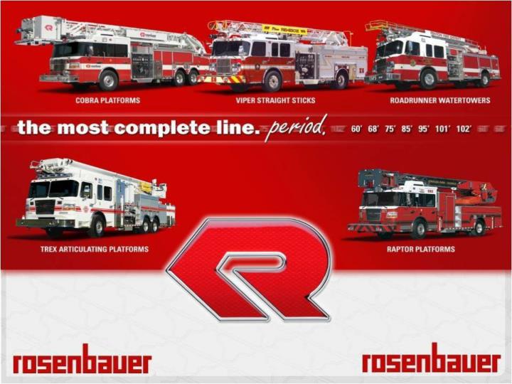
Pasco, WA Aerial Familiarization 109T123s (7312). Safety Information Please read all safety information!. Rosenbauer. Safety Introduction. Familiarize yourself with all manuals supplied Read and follow all safety precautions

E N D
Pasco, WA Aerial Familiarization 109T123s (7312)
Safety Information Please read all safety information! Rosenbauer Safety Introduction Familiarize yourself with all manuals supplied Read and follow all safety precautions Do not modify any equipment without authorization from customer service Keep ignition sources away from flammable objects Practice good housekeeping
For the safety of everyone on your crew. A safety harness MUST BE WORN at ALL TIMES by any individual on the aerial! Safety Harnesses
Determine if the aerial will be used as a water tower or for rescue. Make sure to note ALL overhead obstructions. Scan scene to position the truck for best attack. NOTE: For the best positioning, a corner of a building is highly suggested. This gives the operator access to two sides of the structure as well as the roof. REMINDER: The operator should always observe the placement of the fire fighting vehicle to be sure that there is enough space for the stabilizers to be set and the aerial to be operated without any obstructions. Obstructions to be most aware of include, but are not limited to: adjacent buildings, curbs, drop-offs at road edges, man holes, vehicles, trees, over head electrical wires, ditches and culverts. Positioning the Truck for Operation
Advantages: Can reduce the truck’s grade by extending the rear outrigger stabilizer jacks. When truck is set up the front tires will be in contact with the ground. With the outriggers set operator has more ballast for the operation of the aerial. SETTING FRONT OF TRUCK TO UPHILL GRADES With maximum grades the truck should be positioned with the cab facing uphill. Aerial should be operated over the rear.
Disadvantages: Since only the front tires are on the ground there is less resistance to prevent truck movement. The rear compartment and aerial access step are more difficult to access. SETTING FRONT OF TRUCK TO UPHILL GRADES
Advantages: Rear compartments are closer to the ground for easier access. Better resistance to keep the truck from sliding by having more tires in contact with the ground. SETTING FRONT OF TRUCK TO DOWNHILL GRADES
Disadvantages: Can not reduce the trucks grade by extending the front outrigger stabilizer jacks. FRONT TIRES MUST STAY ON THE GROUND WHEN OPERATING OVER THE FRONT OF THE TRUCK. It is possible that the truck will teeter if the aerial is operated over the front stabilizers with the front tires off the ground. Their will be less ballast for aerial operations with the rear tires on the ground. When setting up the stabilizers the ground must be firm. It is highly recommended that the operator uses the outrigger pads provided. Setting up over manholes, underground parking facilities or storm drains could cause serious damage to the operator and/or serious damage to the truck. The area must be able to support 75 PSI. SETTING FRONT OF TRUCK TO DOWNHILL GRADES
EXHAUST FUMES Be conscious of exhaust fumes when working around the vehicle. Ensure that there is adequate ventilation. DO NOT alter emission controls. Safety Around the Vehicle • COOLING SYSTEM • Ensure there is adequate clearance between fan and shroud. • DO NOT alter fan ratio, spacers or position. • Observe fan clutch operation to ensure fan is disengaging when cooling is not necessary. • AIR INTAKE SYSTEM • DO NOT alter any intake piping or filter locations.
UNDERCARRIAGE Notify others when working underneath the vehicle. Keep away from moving parts. Avoid hot areas such as engine, transmission, exhaust and pumps. Avoid ports that may eject steam or other hot fluids. Safety Around the Vehicle • COVERS AND DOORS • DO NOT sit, stand, climb or hang on open doors. • Some doors are spring loaded. Use caution when opening doors. • Use care not to get fingers and hands caught in pinch points such as hinges. • Do not drive with doors partially closed. • TIRES AND WHEELS • Deflate tires prior to removal. • DO NOT operate vehicle with damaged or improperly inflated tires.
ENTERING, EXITING AND CLIMBING Keep steps, handles, rails, walking surfaces and shoes free from grease. Use extreme caution during inclement weather or when surfaces are wet. DO NOT use pump fixtures or lights as stepping surfaces. DO NOT stand near hose when vehicle is moving. Vehicle Safety • Make deliberate movements when entering, exiting or climbing on the vehicle. DO NOT rush. • DO NOT climb in areas without slip resistant surfaces and hand holds. • Use a three point stance in which three extremities are in contact with the vehicle, when entering, exiting or climbing on the vehicle.
VEHICLE BACKING Use a spotter when backing vehicle. Establish hand or verbal communication prior to backing. During periods of low light use spotter with wands and reflective vests. Vehicle Operational Safety • VEHICLE CONTROL • Ensure proper tire inflation before operating vehicle. • A neutral safety switch prevents vehicle from being started in gear. • Allow starter to cool for one minute if vehicle doesn’t start within 15 seconds. • Familiarize yourself with gauges, switches and on-board accessories prior to operating vehicle.
WATCH YOUR TURNING Increased overhangs, particularly at the rear, must be kept in mind. NOTE: In narrow crossings the driver must confirm that there is enough space for turning.
KNOW YOUR TRAVEL HEIGHT NOTE: The driver must confirm the vehicle can freely pass low underpasses.
KNOW YOUR TOTAL WEIGHT NOTE: The driver must confirm the vehicle can freely pass limited weight areas.
WATCH YOUR ANGLE OF DEPARTURE GROUND CLEARANCE AND THE ANGLES TO FRONT AND REAR STRUCTURES.
REMEMBER HIGH CENTER OF GRAVITY HEIGHT OF THE CENTER OF GRAVITY. NOTE: Speeding with the vehicle when turning a corner is DANGEROUS! REMEMBER 60% OF YOUR WEIGHT IS ABOVE YOU
Rosenbauer 109’ Viper Aerial Rosenbauer Commander Flat Roof Cummins ISX 500 hpEngine Waterous CSU 2,000 gpm pump 400 gallon water tank Green Star genset system
Before tilting cab check the following: Front bumper storage lid is closed. No equipment on front bumper. Inside cab -all loose equipment removed such as air packs, books, portable radios, helmets, etc CAB TILT PROCEDURES
Raise the Aerial to 20 degrees Shut the engine down Leave battery switch on Go to right side pump panel compartment Operate switch to raise cab YOU MUST SET THE JACKSAND RAISE THE AERIAL BEFORE TILTING CAB!
Check to see if area is clear to lower cab! Raise cab fully Pull cable until cab safety lock is away from the cab cylinder and hold Hold switch down Cab will automatically lock down LOWERING CAB
Pump and Plumbing info Waterous 2000 GPM pump Stainless Steel plumbing Discharges Crosslays 2-1/2” Discharges LDH Discharges 25
ANTI-ELECTROCUTION PLATFORM The pump control panel operator should stand on anti-electrocution platform when the aerial is being operated. Standing on the anti-electrocution platform will raise the pump operator off the ground and keep the operator from being a pathway to ground for electrical current if the aerial contacts and energized line.
Pump Engagement Neutral Switch from Road to Pump Shift to 4th gear 29
Drains 30
Generator has a monitoring system that lets you see amps, line voltage, and frequencies. Breaker panel box is equipped with GFI breakers. GENERATOR ELECTRICAL PANEL
Aerial Types: Mid-Mounted Aerial Ladder Rear-Mounted Aerial Ladder Mid-Mounted Aerial Platform Rear-Mounted Aerial Platform Aerial Vocabulary Base-Section – the lowest most section on an aerial Mid-Section – is any of the sections used between the base section and the fly section Fly-Section – the top most section on an aerial Short-Jack Operation – allowing aerial to operate in predefined zones with outriggers/stabilizers not fully extend Aerial Vocabulary
Torque Box (tube) – part of an aerial attached below the turntable to transfer torsion loads to the chassis and outriggers. Turntable – part of the aerial device attached to the base ladder section designed to articulate the position for rescue or firefighting E-Tracking - a flexible track utilized to protect electrical, communication and control wires in aerial extension/retraction Soft-Touch Control- electric control of aerial functions through the use of a remote manual control programmed to slowly start and stop aerial functions Auto-Bedding Control – automatic aerial bedding when aerial is in predefined zone Dead Load – weight of aerial and attached mechanism and equipment Live Load (Tip Load) – weight and forces exerted on the aerial by payload, and water stream reactions. Outrigger/stabilizer – a hydraulic lifting mechanism designed to prevent aerial overturn and transfer loads to the ground Aerial Vocabulary
Rated Capacity – total weight of payload at the outermost ladder rung or platform according to ladder load chart Cab-Body Collision Protection – program preventing aerial device from collision with chassis and equipment mounted on the body Pinable Waterway – manual device designed to place the waterway at the tip or next lower section Modified Warren Bridge – design of aerial structure to transfer loads up and down the aerial device. Bolt-On Egress – outermost extension device designed for personnel to climb on/off the end of the aerial Yield Strength – point at which the material exhibits a permanent deformation or set Water Load – stress produced by water weight and nozzle reaction overhead to the side and below stream applications Hot Dipped Galvanized – a process for treating steel ladder and stabilizers to prevent corrosion and oxidation on the inside and outside of all the ladder parts Aerial Vocabulary
Dead load Stress – stress produced by the aerial structure weight and any permanently mounted or manufactured equipment Rated Capacity Stress – stress produced by the aerial rated capacity applied to the tip of the fly section Water Reaction Stress - weight of the water and nozzle reaction force Material Yield Stress – the stress at which a material exhibits a distortion or permanent set Load Limit Indicators (Load Charts) - a load indicator or instruction plate, visible at the operators position, showing the recommended safe load at any condition of the aerial’s elevation and extension Aerial Vocabulary
109’ 4-Section Rear Mount Aerial • 4 Outriggers with a spread of 15’ 6” • Tip load wet of 500 lbs. Dry 500 lbs • Water flowing at 1000 GPM 90° to the side • Horizontal reach at 0° is 102’ • Elevation of -10° to 75° vertical height • Axel ratings 23,000 front & 54,000 tandem rear • Wheel base 244” • Standard Height – 12’ – 0” • Standard Length – 41’ – 4”
Shift transmission (1) from drive into neutral. Apply the parking brake (2). Switch on the aerial master (3). When the aerial master is switched on there is electrical power to the aerial system. At this time flashing lights on the outriggers will begin to operate. Switch on the Power Take-Off (PTO). Note: It is important to note that step # 4 cannot be performed before step # 3 has been completed and step # 2 cannot be completed until step # 1 has been completed. Some trucks will have the aerial master and PTO switch combined . The transmission must be in neutral (4) or 4th gear for the water pump to be engaged. The parking brake must be set before the ladder power will operate. If the water pump is engaged, the high idle of the aerial will be disengaged. 3 Setting Up Your Cab for Aerial Operation 4 1 2
Once the ladder power is activated, the flashing light (1) on the inside of the outrigger jack tubes will begin to flash and the outrigger jack scene lights (2) will come on. Outriggers are ready to operate. Outrigger Operation Set Up 1 1 2
Move Outrigger On/Off Switch to the ON position This will cause the high idle to engage and the warning alarm will begin. The alarm alerts all other personnel the outriggers are being positioned. If the water pump is engaged the high idle of the aerial will be disengaged. Outrigger Operation Set Up With tire chocks set the operator will proceed to the outrigger station. The Outrigger Not Extended Light will be illuminated. This light will stay illuminated until all outriggers have been fully extended and are making contact with the ground. 1
Use Controllers to Extend Outriggers. The outrigger controls are located to the back, outside of the truck to provide the operator a good clear vision to set up the outriggers. The controllers are designed to move in the same direction as the corresponding outrigger. (Example: To extend the right outrigger you would push the controller to the right to extend and to the left to retract.) Position outrigger pads under jack locations Outrigger Operation Set Up
Lower outrigger jacks The controllers are designed to move in the same direction as the corresponding outrigger. (Example: To lower the right outrigger you would push down on the controller.) Take the bubble out of the truck tire or level truck as much as possible. As the truck is leveled or the bubble is taken out, each Jack Indicator Light (3) will respond according to how the outrigger is set (see different setting under Jack Indicator Light description on the control panel). Once all outrigger beams are fully extended and making contact with the ground the Outrigger Not Extended Light will go out. Outrigger Operation Set Up 3 3 3 3
When outriggers are set move the Outrigger On/Off Switch to the OFF position. Install outrigger jack safety pins. Safety pins are not required for operating the aerial. However, we strongly recommend installing them as an additional back up safety feature. Outrigger operation set up is completed. Outrigger Operation Set Up 1 Should any two outriggers at any point come off the ground the aerial will come to a feather-soft stop. The operator will need to retract and raise the aerial out of the unsafe position. Once the aerial is in a safe position the aerial can continue operations as normal.
1. Outrigger On/Off Switch 2. Aerial/Outrigger Override Switch 3. Jack Lights 4. Outrigger Not Extended Light 5. Hour Meter Emergency Hydraulic Backup Pump Switch Change Hydraulic Filter when Light is On Outrigger Control Panel Diagram 5 4 3 3 3 3 2 6 7 1
Outrigger On/Off Switch The Outrigger On/Off Switch must be turned on before the outriggers can be operated. This will enable the high idle if water pump is not engaged. Outrigger On/Off Switch 1