Download
1 / 89
910 likes | 1.11k Vues
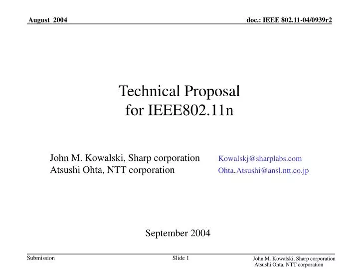
Technical Proposal for IEEE802.11n. John M. Kowalski, Sharp corporation Kowalskj@sharplabs.com Atsushi Ohta, NTT corporation Ohta . Atsushi@ansl.ntt.co.jp. September 2004. Basic Concepts of Our Technical Proposal.

E N D
Technical Proposal for IEEE802.11n John M. Kowalski, Sharp corporation Kowalskj@sharplabs.com Atsushi Ohta, NTT corporation Ohta.Atsushi@ansl.ntt.co.jp September 2004 John M. Kowalski, Sharp corporation Atsushi Ohta, NTT corporation
Basic Concepts of Our Technical Proposal The five criteria requires broad market potential, technical and economic feasibilities for IEEE802.11n standard. • Creating a new standard that limits mandatory requirements to feasible technologies and minimizing the difference from the legacy standards such as IEEE802.11a. • Simple solution makes the standard feasible and it possible to provide various kinds of devices including PCMCIA card type. • This approach will speed the adoption of the standard in the marketplace by making it easier to integrate with the present 802.11 solutions available in the marketplace. Note: If there is any difference between this presentation and the Technical Proposal (Word Document), the Technical Proposal will be the document that represents our proposal. John M. Kowalski, Sharp corporation Atsushi Ohta, NTT corporation
Outline of Our Technical Proposal Main feature of PHY Layer • 2 Tx chains is mandatory. 3 and 4 Tx chains are optional. • Channelization greater than 20MHz is out of scope. • Modified scattered-type preamble for MIMO channel estimation is newly introduced. • Pilot preambles to track time varying channels can be inserted flexibly for reliable long burst transmission. • EXTENDED SIGNAL and MIMO packets are encapsulated after the Legacy PLCP header including PLCP preamble and legacy SIGNAL in order to keep backward compatibility with legacy devices, • Most of all other specifications on PHY layer are the same as that of 802.11a with the exception of MIMO communication function and addition of an new PHY mode of 64QAM R=7/8; this results in minimizing impacts of modifications for 802.11n. John M. Kowalski, Sharp corporation Atsushi Ohta, NTT corporation
Proposed PHY modes (Mandatory modes) All PHY modes (including Mandatory and Optional) occupy bandwidth of 20MHz only. *Channelization greater than 20MHz is Out of Scope. 1. Mandatory PHY modes (1) SISO modes (2) 2x MIMO modes ・ BPSK R=1/2 6 Mbit/s ・ BPSK R=3/4 9 Mbit/s ・ QPSK R=1/2 12 Mbit/s ・ QPSK R=3/4 18 Mbit/s ・ 16QAM R=1/2 24 Mbit/s ・ 16QAM R=3/4 36 Mbit/s ・ 64QAM R=2/3 48 Mbit/s ・ 64QAM R=3/4 54 Mbit/s ・ 64QAM R=7/8 63 Mbit/s ・ BPSK R=1/2 12 Mbit/s ・ BPSK R=3/4 18 Mbit/s ・ QPSK R=1/2 24 Mbit/s ・ QPSK R=3/4 36 Mbit/s ・ 16QAM R=1/2 48 Mbit/s ・ 16QAM R=3/4 72 Mbit/s ・ 64QAM R=2/3 96 Mbit/s ・ 64QAM R=3/4 108 Mbit/s ・ 64QAM R=7/8 126 Mbit/s *Coding rate R=7/8 is newly added. John M. Kowalski, Sharp corporation Atsushi Ohta, NTT corporation
Proposed PHY modes (Optional modes) 2. Optional PHY modes (1) 3x MIMO modes (2) 4x MIMO modes ・ BPSK R=1/2 18 Mbit/s ・ BPSK R=3/4 27 Mbit/s ・ QPSK R=1/2 36 Mbit/s ・ QPSK R=3/4 54 Mbit/s ・ 16QAM R=1/2 72 Mbit/s ・ 16QAM R=3/4 108 Mbit/s ・ 64QAM R=2/3 144 Mbit/s ・ 64QAM R=3/4 162 Mbit/s ・ 64QAM R=7/8 189 Mbit/s ・ BPSK R=1/2 24 Mbit/s ・ BPSK R=3/4 36 Mbit/s ・ QPSK R=1/2 48 Mbit/s ・ QPSK R=3/4 72 Mbit/s ・ 16QAM R=1/2 96 Mbit/s ・ 16QAM R=3/4 144 Mbit/s ・ 64QAM R=2/3 192 Mbit/s ・ 64QAM R=3/4 216 Mbit/s ・ 64QAM R=7/8 252 Mbit/s *3 and 4 Tx chains are optional. All PHY modes use convolutional coding (R=1/2 or punctured versions of it, constraint length is 7, which is the same as IEEE802.11a PHY mode). John M. Kowalski, Sharp corporation Atsushi Ohta, NTT corporation
IEEE802.2 LLC Sub-Network Access Protocol (SNAP) MAC Layer Management Entity (MLME) MAC Layer Station Management Entity (SME) PHY Layer Convergence Protocol (PLCP) PHY Layer Management Entity (PLME) PMD #1 PMD #2 PMD #3 PMD #4 Proposed Reference Model • There is a single PHY-SAP that is between MAC and PHY layers; this maintains the basic architecture. • In case of MIMO communication, the number of used PMDs (Physical Medium Dependent) are adaptively changed according to its number of Tx chains. The PLCP sublayer is responsible for conversion between a serial data stream and divided data sub-streams. John M. Kowalski, Sharp corporation Atsushi Ohta, NTT corporation
Outline of our technical proposal (cont'd) Main features of MAC Layer • MSDUs that belong to the same TID and sent to the same reception address can be aggregated in a MAC frame in order to improve MAC efficiency. • Each MSDU in an aggregated frame is selectively re-transmitted in SR-ARQ manner. • Bit-map-type multiple ACK is introduced instead of block-ACK based on 802.11e. • Random back-off mechanism is slightly modified, and unnecessary contention window extension that is not caused by contention can be avoided. • Optional highly accurate synchronization function between stations is introduced. • Signaling to control use of Tx and Rx resources is introduced. John M. Kowalski, Sharp corporation Atsushi Ohta, NTT corporation
IEEE802.11n MAC Layer Specification John M. Kowalski, Sharp corporation Atsushi Ohta, NTT corporation
max 217-1 octets octets: 2 2 6 6 2 2 4/0 3-511 4 Address2 Aggregation Information Aggregated Frame Body Address1 Header FCS TLS Frame Control Duration /ID Aggregated Frame Sequence Control QoS Control MAC header MSDU Aggregation in IEEE802.11n MAC Frame • To improve MAC efficiency, a new MAC frame is proposed in which transmitted MSDUs are aggregated in a MAC frame (next slide). The maximum number of aggregated MSDUs is 255. • Frame Control, Duration ID, Address1, Address2, QoS Control, Aggregation Information, Aggregated Frame Sequence Control and Header FCS are present in all aggregated frames • TLS field is only present in certain frame types and subtypes. • This MAC frame can be used in WDS without any modification. Aggregation Information ・“MSDU Count" field shows how many MSDUs are contained in this MAC frame body. ・“Length #k" shows the length of data for the k-th MSDU. John M. Kowalski, Sharp corporation Atsushi Ohta, NTT corporation
New Frame Types John M. Kowalski, Sharp corporation Atsushi Ohta, NTT corporation
MSDU Aggregation in IEEE802.11n MAC Frame (cont.) • Sequence Control for each MSDU, and FCS. • With individual MSDU check, Selective Repeat ARQ can be done. John M. Kowalski, Sharp corporation Atsushi Ohta, NTT corporation
IEEE802.11n ACK Frame Format and SR-ARQ Aggregation Frame body of the received Aggregated Frame 6 6/0 2 4 6 6/0 2 4 6 6/0 2 4 octets: AddressA #1 AddressA #N AddressB #1 MSDU #1 data AddressB #2 MSDU #2 data AddressB #N MSDU #N data MSDU FCS #1 AddressA #2 MSDU FCS #2 MSDU FCS #N MSDU Sequence Control #2 MSDU Sequence Control #1 MSDU Sequence Control #N Receiving Status Receiving Status Receiving Status B0 BN BN+1 BM octets: 2 2 6 2 4 1 Agg Ack Bitmap Pad bits Agg Ack Bitmap Receiver Address FCS Agg Ack Bitmap of Aggregated Acknowledgement Bitmap Count AA Control Frame Control Duration /ID Aggregated Acknowledgement AA Control Field John M. Kowalski, Sharp corporation Atsushi Ohta, NTT corporation
IEEE802.11n ACK Frame Format and SR-ARQ (cont.) • The 802.11n ACK frame contains a maximum of 255 bit bit-map-ACK field which indicates the reception results for FCS#1-FCS#N • When a receiver successfully detects a 802.11n MAC header and its MAC address matches the receiver address in the MAC header, it sends 802.11n ACK frame. • The bit-map-ACK field may contain all NAKs if the MAC header is correctly received and the following MSDUs are all errored. Because this means a contention has not occurred at the time, the transmitter can keep the contention window size to be minimum value. • The AggAckFlag in the AA Control Field indicates if a AggAck bit-map field is available or not. • The 2 bit Rate Feedback Information in the AA Control Field is the information from the receiver to for a closed loop rate control. • After receiving the 802.11n ACK frame, the transmitter can selectively re-transmit MSDUs which are informed to be NAK and transmit newly input data together within a next MAC frame. • To guard against the “Lost Ack” problem, an AggAckReq frame is introduced. John M. Kowalski, Sharp corporation Atsushi Ohta, NTT corporation
Aggregation Functional Description (1) • Basic Philosophy: • previously unsent MSDUs can be included in an aggregated frame that includes retried MSDUs for increased efficiency • frames go up to the receiver MAC SAP in order (although frames may never be received), • the receiver is agnostic to expiration of retried frames like legacy • Stations maintain re-try counters (or Delay Bound for HCCA) for each MSDU. • When each MSDU exceeds its retry limit or delay bound, no further transmission attempts of that MSDU are made. • Aggregated Frame Sequence Control Field updated on re-transmission of Aggregated Frame (less any expired MSDUs), to ensure that ACK bitmap is tracked with Aggregated Frame. John M. Kowalski, Sharp corporation Atsushi Ohta, NTT corporation
Aggregation Functional Description(2) • There is never more than 1 pending Aggregated Frame made to any one destination from any one source. • These rules are a simple extension of current mechanisms in 802.11 and 802.11e. • The receiver can be agnostic to the number of retries per MSDU. 802.11n AggAckReq Frame John M. Kowalski, Sharp corporation Atsushi Ohta, NTT corporation
Receiver Side Transmitter Side Start (Frame Transmission) Start (Frame Reception) AggAckReq? Yes AggAck frame Reception? No No Yes CW=CWmax? HT-indication bit=1? No Yes No Yes Expand Contention Window size (CW=2x[CW+1]-1) Successfully received MAC Header? Reset Contention Window (CW=CWmin) Yes Rx address Check? No No Yes Transmit AggAck frame End End Random Backoff Rule ・When a receiver successfully detects a 802.11n MAC header and its MAC address matches the receiver address in the MAC header, it sends 802.11n ACK frame. ・The bit-map-ACK field may contains all NAK if the MAC header is correctly received but following MSDUs are all errored. Because this means a contention has not occurred at the time, the transmitter can reset the contention window size to CWmin. 25 John M. Kowalski, Sharp corporation Atsushi Ohta, NTT corporation
Support for Link Synchronization: Capability Advertisement Synchronization Capability Element • The format of this element is a non-negative integer representation whose value, if given by Synchronization Precision, communicates that the achievable synchronization is 4ms X 2-SynchPrecision. When the value of SynchPrecision is 0, MSDU TimeStamps are not transmitted from an 802.11n station. • This allows STAs to associate with APs and establish streams to STAs that match supported synchronization capability to the application. Synchronization presentation: 11-04-775 John M. Kowalski, Sharp corporation Atsushi Ohta, NTT corporation
Support for Link Synchronization: Timestamp for Link Synchronization Octets 1 1 1 1 Integer most significant octet Integer least significant octet Most significant Fraction of 1s Least significant Fraction of 1s Fractional part Integer part Implied binary point • The TLS is a 4 octets time stamp updated by the clock of the STA transmitting the aggregated frame. The two most significant octets are integers. The least significant two octets are in fractional units of 1ms, i.e., the most significant bit of the most significant octet of the Fractional part is ½ microsecond, the next most significant bit of the most significant octet of the Fractional part is ¼ microsecond and so forth. By transmitting this way, the maximum value of the integer part is 216 -1 microseconds, and the smallest precision that is sent is 0.15 nanoseconds. John M. Kowalski, Sharp corporation Atsushi Ohta, NTT corporation
Frame Formats for Resource and Functionality Negotiation • Resources for High Throughput may be signaled “quasi-statically” to, e.g., negotiate limiting usage of High Throughput Resources when it is desirable to save power at the expense of occupying medium time. • AP acts as arbitrator. • Follows TSPEC signaling in 802.11e. John M. Kowalski, Sharp corporation Atsushi Ohta, NTT corporation
IEEE802.11n PHY Layer Specification John M. Kowalski, Sharp corporation Atsushi Ohta, NTT corporation
802.11n PLCP Basic Frame (1) SISO mode Legacy PLCP Preamble(4) Legacy Signal(1) Extended Signal(1) PSDU(variable) (2) 2Tx MIMO mode Legacy PLCP Preamble(4) Legacy Signal(1) Extended Signal(1) 2x MIMO Preamble(2) PSDU(variable) (3) 3Tx MIMO mode Legacy PLCP Preamble(4) Legacy Signal(1) Extended Signal(1) 3x MIMO Preamble(3) PSDU(variable) (4) 4Tx MIMO mode Legacy PLCP Preamble(4) Legacy Signal(1) Extended Signal(1) 4x MIMO Preamble(4) PSDU(variable) 802.11n PSDU format Tail (1) Service(2) 802.11n MAC Frame(variable) Padding(variable) IEEE802.11n PLCP Frame Format • 4 PLCP formats are defined for SISO, 2Tx, 3Tx and 4Tx chains MIMO modes. John M. Kowalski, Sharp corporation Atsushi Ohta, NTT corporation
Legacy/Extended Signal and How to Keep Backward Compatibility • HT-indication bit in the legacy SIGNAL is used to indicate whether the EXTENDED SIGNAL is after the legacy SIGNAL or not. • Length and Rate bits in the legacy SIGNAL are used to show the physical duration from the EXTENDED SIGNAL to end of the frame, that is obtained by Length/Rate. This is fake information to keep backward compatibility with legacy device. • The EXTENDED SIGNAL is transmitted with fixed PHY mode of QPSK R=1/2. • In the EXTENDED SIGNAL, Number of Tx chains, Rate and length are declared as ACTUAL information. SISO MIMO Legacy Preamble Legacy Signal Extended Signal MIMO Preamble PSDU MIMO Preamble PSDU HT-indication bit John M. Kowalski, Sharp corporation Atsushi Ohta, NTT corporation
Actual information (Extended Signal) # of Tx chains=2, Rate=63Mbps, Length=1386Bytes Duration=88us SISO MIMO Extended Signal Legacy Signal MIMO Preamble PSDU (693Bytes) Legacy Preamble PSDU (693Bytes) MIMO Preamble 88us 12us 100us Fake information (Legacy Signal) Rate=12Mbps, Length=150Bytes (1200bits) Duration=100us How to Keep Backward Compatibility (Example) Case study: Duration from EXTENDED SIGNAL to end of the frame is 100us. • ACTUAL information including Number of Tx chains, Rate and length of the frame body is accommodated in the EXTENDED SIGNAL. • When the duration from EXTENDED SIGNAL to end of the frame is 100us, it is equal to the duration with SISO mode where Rate is 12Mbps and Length is 150 Bytes. • The information (12Mbps and 150 Bytes) is accommodated in legacy Signal as a FAKE information. John M. Kowalski, Sharp corporation Atsushi Ohta, NTT corporation
Pilot Preamble Interval(6) Length(17) Tail(6) Rate(4) Reserved(11) Reserved(1) Number of Tx chains(2) Parity(1) Legacy Signal and Extended Signal Format Legacy Signal Format Length(12) Tail(6) Rate(4) Parity(1) High Throughput Indication(1) High Throughput Indication 0:Legacy 1:802.11n *The reserved bit (B4) in legacy Signal is used as High-Throughput Indication which indicates whether the PLCP frame format is based on 802.11n or not. Extended Signal Format Number of Tx chains 00:1 Tx chain 01:2 Tx chains 10:3 Tx chains 11:4 Tx chains Rate Legacy Signal and 64QAM R=7/8 Pilot Preamble Interval 000000 No Pilot Preamble 000001-111111 Insert Pilot preamble with interval of the value×8OFDM symbols John M. Kowalski, Sharp corporation Atsushi Ohta, NTT corporation
Constraint for Long Burst Transmission Background • Too long occupation for packet transmission degrades transmission delay performance, especially it is critical issue for QoS data flow, In order to guarantee QoS, too long packet transmission should be avoided. • Even in the case of non-QoS data flow, large delay may cause TCP window stall. • In Japanese regulatory, packet transmission exceed 4ms is prohibited. • Though MAC efficiency can be improved by frame aggregation, its effect seems to be saturated around this range. Extended Signal Legacy Signal MIMO Preamble PSDU Legacy Preamble PSDU MIMO Preamble Duration X The maximum duration of PSDU shall be less than or equal to 2.732ms. *2.732ms is the length for 4095 bytes transmitted at QPSK R=1/2. John M. Kowalski, Sharp corporation Atsushi Ohta, NTT corporation
Antenna No. Antenna No. Timing (symbol) Timing (symbol) Existing typical MIMO preambles -Background- Ex). 4x4MIMO case) STC-type preamble Scattered-type preamble C null null null C11 C12 C13 C14 null C null null C21 C22 C23 C24 null null C null C31 C32 C33 C34 null null null C C41 C42 C43 C44 ・ Scattered-type provides less impact to implement MIMO channel estimation function than STC-type. ・ STC-type achieves good SNR performance for MIMO channel estimation. ・ STC-type, however, requires function of multiplying matrixes to estimate MIMO channel estimation. Calculation process for MIMO channel estimation with STC-type preamble John M. Kowalski, Sharp corporation Atsushi Ohta, NTT corporation
Pattern: 1 Pattern: 2 T 2T T 2T time time C2 null null C2 #1 #1 null C2 C2 null #2 #2 Antenna Number Antenna Number N N Proposed MIMO Preamble Feature of the modified Scattered-type MIMO preamble • Scattered pattern for each subcarrier is replaced subcarrier-by-subcarrier for averaging total transmission power from each antenna. • For example, in 2 Tx chains case, scattered pattern 1 is used for odd subcarrier numbers and pattern 2 is used for even ones. • In N Tx chains case, the amplitude for a certain subcarrier with which non-null preamble signal is transmitted is times of that for data transmission, and it improves SNR performance for MIMO channel estimation. • Because average total power is equal to that of STC-type preamble, the times amplitude enlargement does not distort the wave form through the non-linear power amplifier. • With the proposed preamble patterns, the set of coefficient for each scattered pattern provides the minimum Peak to Average Power Ratio (PAPR) value. John M. Kowalski, Sharp corporation Atsushi Ohta, NTT corporation
D C P1: -26 -22 -18 -14 -10 -6 -2 +3 +7 +11 +15 +19 +23 -24 -20 -16 -12 -8 -4 +1 +5 +9 +13 +17 +21 +25 P2: -25 -21 -17 -13 -9 -5 -1 +4 +8 +12 +16 +20 +24 -23 -19 -15 -11 -7 -3 +2 +6 +10 +14 +18 +22 +26 Proposed Scattered 2xMIMO Preamble (2 Tx chains) Pattern: 1 Pattern: 2 time time T 2T T 2T #1 #1 C2 null null C2 #2 #2 null C2 C2 null Antenna Number Antenna Number Pattern 1={ -1, 0, -1, 0, -1, 0, -1, 0, +1, 0, +1, 0, -1, 0, -1, 0, -1, 0, +1, 0, -1, 0, -1, 0, +1, 0, DC, -1, 0, +1, 0, -1, 0, +1, 0, +1, 0, +1, 0, +1, 0, +1, 0, -1, 0, -1, 0, +1, 0, -1, 0, -1, 0 } Pattern 2={ 0, -1, 0, -1, 0, -1, 0, -1, 0, +1, 0, +1, 0, -1, 0, -1, 0, -1, 0, +1, 0, -1, 0, -1, 0, +1, DC, 0, +1, 0, -1, 0, +1, 0, -1, 0, -1, 0, -1, 0, -1, 0, -1, 0, +1, 0, +1, 0, -1, 0, +1, 0, +1 } John M. Kowalski, Sharp corporation Atsushi Ohta, NTT corporation
D C Frequency P1: -26 -23 -20 -17 -14 -11 -8 -5 -2 +2 +5 +8 +11 +14 +17 +20 +23 +26 P2: -25 -22 -19 -16 -13 -10 -7 -4 -1 +3 +6 +9 +12 +15 +18 +21 +24 P3: -24 -21 -18 -15 -12 -9 -6 -3 +1 +4 +7 +10 +13 +16 +19 +22 +25 Proposed Scattered 3xMIMO Preamble (3 Tx chains) Pattern: 1 Pattern: 2 Pattern: 3 time time time T 2T 3T T 2T 3T T 2T 3T #1 #1 #1 C3 null null null null C3 null C3 null #2 #2 #2 null C3 null C3 null null null null C3 #3 #3 #3 null null C3 null C3 null C3 null null Antenna Number Antenna Number Antenna Number Pattern 1={-1, 0, 0, -1, 0, 0, +1, 0, 0, +1, 0, 0, -1, 0, 0, +1, 0, 0, -1, 0, 0, +1, 0, 0, -1, 0, DC, 0, +1, 0, 0, +1, 0, 0, +1, 0, 0, +1, 0, 0, +1, 0, 0, +1, 0, 0, -1, 0, 0, -1, 0, 0, +1 } Pattern 2={ 0, -1, 0, 0, +1, 0, 0, +1, 0, 0, +1, 0, 0, -1, 0, 0, +1, 0, 0, +1, 0, 0, +1, 0, 0, -1, DC, 0, 0, -1, 0, 0, +1, 0, 0, -1, 0, 0, -1, 0, 0, +1, 0, 0, -1, 0, 0, +1, 0, 0, +1, 0, 0 } Pattern 3={ 0, 0, -1, 0, 0, -1, 0, 0, +1, 0, 0, -1, 0, 0, +1, 0, 0, +1, 0, 0, -1, 0, 0, +1, 0, 0, DC, +1, 0, 0, -1, 0, 0, -1, 0, 0, -1, 0, 0, +1, 0, 0, -1, 0, 0, -1, 0, 0, -1, 0, 0, +1, 0 } John M. Kowalski, Sharp corporation Atsushi Ohta, NTT corporation
D C P1: -26 -22 -18 -14 -10 -6 -2 +3 +7 +11 +15 +19 +23 Frequency P2: -25 -21 -17 -13 -9 -5 -1 +4 +8 +12 +16 +20 +24 P3: -24 -20 -16 -12 -8 -4 +1 +5 +9 +13 +17 +21 +25 P4: -23 -19 -15 -11 -7 -3 +2 +6 +10 +14 +18 +22 +26 Proposed Scattered 4xMIMO Preamble (4 Tx chains) Pattern: 1 Pattern: 2 Pattern: 3 Pattern: 4 2T 3T 4T 2T 3T 4T 2T 3T 4T 2T 3T 4T T T T T #1 #1 #1 #1 C4 null null null null null null C4 null null C4 null null C4 null null #2 #2 #2 #2 null C4 null null C4 null null null null null null C4 null null C4 null #3 #3 #3 #3 null null C4 null null C4 null null C4 null null null null null null C4 #4 #4 #4 #4 null null null C4 null null C4 null null C4 null null C4 null null null Antenna Number Antenna Number Antenna Number Antenna Number Pattern 1={ -1, 0, 0, 0, -1, 0, 0, 0, -1, 0, 0, 0, +1, 0, 0, 0, +1, 0, 0, 0, +1, 0, 0, 0, -1, 0, DC, 0, 0, -1, 0, 0, 0, +1, 0, 0, 0, -1, 0, 0, 0, -1, 0, 0, 0, +1, 0, 0, 0, -1, 0, 0, 0 } Pattern 2={ 0, +1, 0, 0, 0, +1, 0, 0, 0, +1, 0, 0, 0, -1, 0, 0, 0, -1, 0, 0, 0, -1, 0, 0, 0, +1, DC, 0, 0, 0, +1, 0, 0, 0, -1, 0, 0, 0, +1, 0, 0, 0, +1, 0, 0, 0, -1, 0, 0, 0, +1, 0, 0 } Pattern 3={ 0, 0, -1, 0, 0, 0, +1, 0, 0, 0, -1, 0, 0, 0, -1, 0, 0, 0, +1, 0, 0, 0, -1, 0, 0, 0, DC, -1, 0, 0, 0, +1, 0, 0, 0, +1, 0, 0, 0, +1, 0, 0, 0, -1, 0, 0, 0, -1, 0, 0, 0, -1, 0 } Pattern 4={ 0, 0, 0, +1, 0, 0, 0, -1, 0, 0, 0, +1, 0, 0, 0, +1, 0, 0, 0, -1, 0, 0, 0, +1, 0, 0, DC, 0 +1, 0, 0, 0, -1, 0, 0, 0, -1, 0, 0, 0, -1, 0, 0, 0, +1, 0, 0, 0, +1, 0, 0, 0, +1 } John M. Kowalski, Sharp corporation Atsushi Ohta, NTT corporation
(≒1: 2 : 3 : 2) Advantages of proposed MIMO preamble • The MIMO channel estimation function is easy to implement because the MIMO channel matrix can be directly obtained without interference cancellation process between antennas. • The amplitude enlargement does not distort the wave form through the non-linear power amplifier, and it can improve SNR performance for MIMO channel estimation. • The proposed Scattered-type preamble shows the superior performance of Peak to Average Power Ratio compared to the legacy long preamble. PAPR performance # of valid subcarriers PAPR Total power Legacy 52 1.000 1.000 P1 0.790 26 1.015 2Tx 0.790 26 1.015 P2 0.750 18 1.046 P1 0.860 17 0.988 P2 3Tx 0.860 17 0.988 P3 0.944 13 1.004 P1 Ratio of amplitude for each subcarrier 0.944 13 1.004 P2 Legacy: 2Tx: 3Tx: 4Tx =64: 91: 111: 128 4Tx 13 0.944 1.004 P3 P4 13 0.944 1.004 John M. Kowalski, Sharp corporation Atsushi Ohta, NTT corporation
Pilot Preamble interval Pilot Preamble interval Pilot Preamble Insertion • Because channel varies over time, the accuracy of channel estimation will degrade over a long burst. • By inserting Pilot-preamble, MIMO channel can be re-estimated once more in the burst. • In the case of MIMO transmission, the pilot preamble is identical to MIMO preamble. • In the case of SISO transmission, the pilot preamble is identical to legacy long preamble. • The interval of the pilot preamble insertion is flexibly selected. • When the Pilot Preamble Interval field is set to be "00000", it indicates no pilot preamble is inserted. H(t) : Time varying MIMO channel matrix at time t Frame body part Extended Signal Legacy PLCP Header Pilot Preamble MIMO Preamble Pilot Preamble Pilot Preamble MIMO Preamble Pilot Preamble Detecting MIMO signal with H(t0) Detecting MIMO signal with H(t1) Detecting MIMO signal with H(t2) H(t0 ) H(t1 ) H(t2 ) time t0 t1 t2 John M. Kowalski, Sharp corporation Atsushi Ohta, NTT corporation
SISO MIMO Extended Signal Tx#1 Legacy Signal MIMO Preamble Legacy Preamble Frame Body MIMO Preamble Tx#4 Frame Body Transmission Power Adjustment Tx#1 Tx Power=P Tx Power=P/N Tx#2 No signal Tx Power=P/N Tx#4 No signal Tx Power=P/N Total Total Power=P (Constant in a burst) Transmission Power Adjustment • SISO signal shall be transmitted from single antenna. This is because transmitting same signals from multiple antenna forms directional beam that makes reception performance unstable. • The transmission power per antenna in the MIMO part shall be suppressed to 1/N times of that in SISO part while the SISO signal is transmitted with available full power in order to keep the transmitted power constant. John M. Kowalski, Sharp corporation Atsushi Ohta, NTT corporation
Ex.) 3 Tx chains case -21Df -7Df 7Df 21Df -21Df -7Df 7Df 21Df -21Df -7Df 7Df 21Df #1 P1(1) P2(1) P3(1) P4(1) P1(2) P2(2) P3(2) P4(2) P1(3) P2(3) P3(3) P4(3) ・・・ Antenna #2 P1(1) P2(1) P3(1) P4(1) P1(2) P2(2) P3(2) P4(2) P1(3) P2(3) P3(3) P4(3) #3 P1(1) P2(1) P3(1) P4(1) P1(2) P2(2) P3(2) P4(2) P1(3) P2(3) P3(3) P4(3) time[symbol] t=1 t=2 t=3 Multiplexed Pilot-subcarrier Transmission • Legacy IEEE802.11a pilot signals are transmitted from each antenna on the pilot-subcarriers. John M. Kowalski, Sharp corporation Atsushi Ohta, NTT corporation
X0 X1 X2 X3 X4 X5 X6 Source Data A0 A1 A2 A3 A4 A5 A6 Stolen bit Encoded Data B0 B1 B2 B3 B4 B5 B6 Bit Stolen Data (received data) A0 B0 A1 A2 A3 B4 A5 B6 A0 A1 A2 A3 A4 A5 A6 Bit Inserted Data Inserted Dummy Bits B0 B1 B2 B3 B4 B5 B6 y0 y1 y2 y3 y4 y5 y6 Decoded Data Punctured Coding (R=7/8) John M. Kowalski, Sharp corporation Atsushi Ohta, NTT corporation
Transmitter Side Receiver Side Encoder Interleaver OFDM Mod. Deinterleaver Decoder MIMO OFDM DEM. Encoder Interleaver OFDM Mod. Deinterleaver Decoder S/P P/S Encoder Interleaver OFDM Mod. Deinterleaver Decoder PHY-SAP PHY-SAP Encoder Interleaver OFDM Mod. Deinterleaver Decoder Basically based on 802.11a/g Encoder/Decoder and Interleaver/Deinterleaver Transmitter Side • Input data to PLCP is divided into N data streams with S/P converter. • Each data stream is encoded and interleaved individually. Receiver Side • Each data stream is deinterleaved and decoded individually. • Received data is reconstructed from N data streams with P/S converter. As for each data stream, the encoder/decoder and the interleaver/ deinterleaver are all based on IEEE802.11a standards. It is quite scalable and it does not require high-speed clock rate operation. John M. Kowalski, Sharp corporation Atsushi Ohta, NTT corporation
120 110 100 90 Number of Tx chains : 2 PHY mode : 64QAM R=7/8 PHY Rate : 126 Mbit/s Ethernet frame size : 1500Bytes CWmin : 15 Error free Pilot preamble interval 80 Expected Throughput [Mbit/s] 70 60 50 40 0 5 10 15 20 25 30 Number of aggregated frames per MAC frame No Pilot Np=128 Np=64 Frame aggregation and throughput performance In case of 2 Tx chains without pilot preamble, throughput of 116 Mbps can be achieved under the constraint of maximum PSDU duration of 2.732 ms. John M. Kowalski, Sharp corporation Atsushi Ohta, NTT corporation
Simulation Methodology John M. Kowalski, Sharp corporation Atsushi Ohta, NTT corporation
Simulation Methodology - Outline - • This simulation methodology is mainly based on “Unified “Black Box” PHY Abstraction Methodology” (IEEE 802.11-04/0218r3). • With the aim of high-speed simulation, we classified the total simulation into following three steps that do not require co-simulation; (1) PHY Simulation • PHY simulations are run to obtain Look Up Tables (LUTs), which are the tables of Channel Capacity (CC) vs. PER for all PHY modes and channel models. (2) Pre-MAC Simulation • With TGn channel model, time varying MIMO channel is simulated. • Time varying PER is estimated by CC value for the MIMO channel, and it is recorded in a PER data file. (3) MAC/System Simulation • MAC/System level simulation is executed with time varying PER that is recorded PER data files for all links. John M. Kowalski, Sharp corporation Atsushi Ohta, NTT corporation
Model # Channel Model Channel Data rates PHY Model Black Box PHY performance CC Capacity Calc. Look Up Table PHY Simulation • By using “Unified “Black Box” PHY Abstraction Methodology” (IEEE 802.11-04/0218r3) approach, relationship between CC (Channel Capacity) and PER for all PHY modes can be obtained. • By generating time varying MIMO channel, test packets with fixed length are transmitted and checked whether it is successfully transmitted or not. • The transmission result and its CC value are recorded once and they are analyzed to generate the LUT for the fixed PHY mode and the length. John M. Kowalski, Sharp corporation Atsushi Ohta, NTT corporation
DistanceModel # Look Up Table Channel Model Channel RequiredPER CC Recommended PHY mode and its PER Capacity Calc. PER[t] Data Filefor a Certain Link Pre-MAC Simulation • By using the TGn channel model, a time varying MIMO channel for a certain distance can be generated. • The instantaneous PER for a certain PHY mode is estimated by referring LUT for the calculated CC value of the MIMO channel. • The most efficient PHY mode with which the target PER can be satisfied is selected and the time varying PER data is recorded in a PER[t] data file • When there are some links in a certain simulation scenario, PER data files for the all links are necessary. John M. Kowalski, Sharp corporation Atsushi Ohta, NTT corporation
Model #Required PER PER, PHY mode Link No.Length time PERCalc. MAC /SystemModel PER[t] Data File#1 PER[t] Data File#2 PER[t] Data File#n MAC/System Simulation • When a MAC simulator generates a data packet on a certain link, it refers the instantaneous PER at the time from the PER[t] data file related for the link. Packet error is simulated with the instantaneous PER value. • When the length of transmitting packet does not match the fixed length on the PHY simulation, the simulator approximately converts the PER value. In this approximation, we simply assume that BER is constant within a packet. John M. Kowalski, Sharp corporation Atsushi Ohta, NTT corporation
Simulation Parameters John M. Kowalski, Sharp corporation Atsushi Ohta, NTT corporation
Simulation parameters for PHY and pre-MAC simulation Items Parameter Number of Tx and Rx antennas 1x2 (SISO) or 2x2 (MIMO) BPSK, QPSK, 16QAN, 64QAM Subcarrier modulation Convolutional cording and Viterbi decoding Forward error correction 1/2, 2/3, 3/4 and 7/8 Cording rate 7 Constraint length 52 Number of subcarriers 312.5 kHz Subcarrier frequency spacing 1500 bytes MSDU length IEEE802.11n channel model B and E MIMO channel model 0 dBi omni directional antenna Tx and Rx antenna The antenna separation is 1/2 wavelength Impairments IM1, IM5 and IM6 are considered.* Output backoff 11dB for all 2x2 MIMO PHY modes / 8dB for SISO modes Signal detection scheme Maximum likelihood detection (MLD) * The definition is described in Comparison Criteria document John M. Kowalski, Sharp corporation Atsushi Ohta, NTT corporation
Considerations for MAC/System simulation • No hidden stations. The longest distance is 70m for SS6. If the transmitting power is 14dBm, the station at 70m receives -78dBm with Channel Model E. Supposing that the receiver must detect at least -82dBm, we considered that there is no hidden stations • Error free for Control Frames. Control Frames are all in 24MBps SISO mode, making the PER of Control Frames very low. • Use only AIFS for Backoff. Since there is no hidden stations, contention happens only at PLCP header. In addition, Ack (Control) Frames are error free. Therefore, the only case to use EIFS in EDCA Backoff is when there’s error in the MAC header. Since we set the PHY rate to small PER[t] for frames of 1500 byte, the MAC header error rate is too small. • PER[t] data files are adjusted according to eachflow’s PLR. (next slides) John M. Kowalski, Sharp corporation Atsushi Ohta, NTT corporation
Frame types used for simulation John M. Kowalski, Sharp corporation Atsushi Ohta, NTT corporation
Data transfer pattern for HCCA Ex: many in SS1 and SS6 Ex: VoIP in SS6 AP to STA AP to STA to AP AggAck Agg Data Agg Data +CF poll S S S S P AggAck AggAck Agg Data STA to AP DLP Ex: STA5 to STA 6 in SS1 QoS CF-Poll QoS CF-Poll AggAck AggAck S S P S S P QoS Null Agg Data Agg Data S S Ex: STA10 to AP in SS1 AggAck frame from AP S: SIFS P: PIFS frame from STA HCCA scheduling algorithm based on: A. Nishikawa, H. Fujii, H. Azuma, Y. Ohtani, N. Urano: “QoS control technology in Wireless AV Communication System”, Sharp Technical Journal , vol. 87, Dec. 2003. John M. Kowalski, Sharp corporation Atsushi Ohta, NTT corporation
Simulation parameters for CC3, CC18, CC19, CC20, and CC24 (1/2) • Simulation time and PER[t] data file size are selected according to required PLR. • Examples: Repeat until the end of simulation required number of MSDUs to achieve PLR SS1 minimal simulation time required to achieve required PLR Simulation time for SS1: 70000s (19.4h) Selected according to delay bound SS6 Simulation time for SS1: 60000s (16.7h) More details for each flow setting in Appendix A of the Technical Proposal John M. Kowalski, Sharp corporation Atsushi Ohta, NTT corporation
Simulation parameters for CC3, CC18, CC19, CC20, and CC24 (1/2) SS1 Simulation Parameters 1/2 SS1 Simulation Parameters 2/2 SS6 Simulation Parameters Game & Video Console+Internet More details for each flow setting and simulation results are in Appendix A of the Technical Proposal John M. Kowalski, Sharp corporation Atsushi Ohta, NTT corporation
Aggregated Frame Random Backoff time SIFS (16us) AIFS AggAck PI (Pilot preamble interval) Mean Cycle Simulation parameters for CC27 and CC28 SS16 Simulation Parameters This simulation uses AC_BE John M. Kowalski, Sharp corporation Atsushi Ohta, NTT corporation