Download
1 / 16
170 likes | 351 Vues
Unified Software Process Requirements Analysis & Software Design (Elaboration). Software Engineering November 8, 2014. Overview of USP. Requirements Elicitation (Definition). Problem Statement & User Needs. Use Case Model. Requirements Elaboaration (OO-Analysis).

E N D
Unified Software ProcessRequirements Analysis& Software Design(Elaboration) Software Engineering November 8, 2014
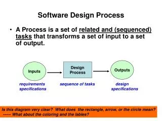
Overview of USP Requirements Elicitation (Definition) Problem Statement & User Needs Use Case Model Requirements Elaboaration (OO-Analysis) The process of defining and modeling the Problem Space The process of defining and modeling the Solution Space Object-Oriented Design Analysis Model Mapping design to Implementation Space Design & Deployment Models Object-Oriented Implementation (Programming) Code in an OOPL (Ada95) (C++)(Java) ComponentModel
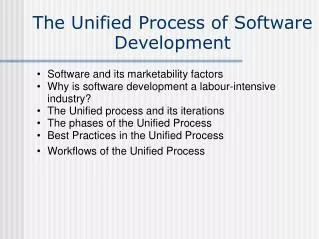
Overview of USP Birth Death • Inception • Elaboration ( focus on “Do-Ability” )(Architecture + high-fidelity cost est.) • Develop detailed use cases(80% of use cases). • Develop a stable architecturalview of the system using the Analysis Model, Design Model, Implementation Model, and Deployment Model. • Create a baseline system specification (SRS). • Produce the Software Development Plan (SDP)which describes the next phase. • Construction • Transition Inception Elaboration Construction Transition Itera- tion Itera- tion Itera- tion Itera- tion Itera- tion Itera- tion Itera- tion Itera- tion Itera- tion Itera- tion … … Arch. DesignDesign Refinement (Analysis Model) (Design Model)
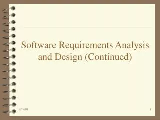
Software RequirementsSpec UML Process and Artifacts 1: Requirements Elicitation (Capture) 2: Requirements Elaboration (Analysis &Specification) 3: Software Design Use Case Model Partition Software into Work packages. Estimate cost, resources, Size, and schedule. Software DevelopmentPlan State Chart CommunicationDiagram Use Case Diagram Define InternalView of System Identify Subsystems Identify Classes & Objects Allocate Functional Responsibilities Analysis Model Model System/Gui behavior Model Use Case External behavior Define SystemBoundary; Identify Actors And ExternalInterfaces; Identify Use Cases Model Use Case Flow Activity Diagram Architecture Diagram CommunicationDiagram Class Diagram Identify Packages their Interfaces & Relationships Model Use Case Internal behavior Identify Boundary, ControlEntity Classes and their Relationships
Requirements Elaboration • Purpose • Identify the Analysis classes and/or subsystems whose instances are needed to perform the use case’s flow of interactions. • Allocate the functional responsibilities of use cases to interacting objects and/or to participating subsystems. • Define functional requirements for operations and encapsulated data of analysis classes and/or subsystems and their interfaces. • Capture detailed design requirements for each use case. • Prioritize use cases and subsystems for further development • Plan the design and construction activites, estimate size, effort, schedule and cost. • Identify Participating Analysis Classes For each use case, identify the problem data that enters and leaves the system via that use case. Identify the problem data that must persist within the system to support other use cases; this is data that must be shared by use cases related on the Use Case Diagram. Assign boundary classes to handle problem data crossing the system boundary. • Describe Analysis Object Interactions • Construct communication diagrams containing participating actors, analysis objects, and message transmissions among them. If necessary, create separate diagrams for distinct sub-flows determined by the same use case. • A use case should be invoked by a message from an actor to an analysis object. • Messages flowing between objects should be labeled with the action requested of the receiving object; these messages define the functional responsibilities of the receiving object. • Support the collaboration diagram with narrative to clarify details. • Artifacts of Analysis • Analysis Class Diagrams (UML) – static architectural design • Activity Diagram (UCM) – dynamic flow of use cases or sub- use cases • Communication Diagrams (UML) – dynamic architectural design • Statecharts/Diagrams (UML) – dynamic architectural design • Use Case Coverage Table – architecture completeness; basis for integration and system testing
Software Requirements Specification (SRS)1 • Title • TOC 1. Introduction 1.1 Purpose 1.2 Scope 1.3 Definitions, Acronyms, and Abbreviations 1.4 References 1.5 Overview 2. Overall Description 2.1 Product Perspective 2.2 Product Functions 2.3 User Characteristics 2.4 Constraints 2.5 Assumptions and Dependencies 3.0 Specific Requirements … next slide 1 IEEE Std 830-1998
Software Requirements Specification (SRS) 3.0 Specific Requirements 3.1 External Interfaces 3.2 Functions 3.3 Performance Requirements 3.4 Logical Database Requirements 3.5 Design Constraints 3.6 Software System Quality Attributes 3.7 Object Oriented Models 3.7.1 Analysis Class Model (Static Model) 3.7.2 Analysis Collaborations (Dynamic Model) 3.8 Additional Comments • Index • Appendices
Software Development Plan (SDP)2 • Front Matter (Title, Toc, Lof, Lot) 1. Overview 1.1 Project Summary 1.2 Evolution of Plan 2. References 3. Definitions 4. Project Organization 5. Managerial Process Plans 5.1 Start-up Plan 5.2 Work Plan 5.3 Control Plan 5.4 Risk Management Plan 5.5 Closeout Plan 6. Technical Process Plan 7. Supporting Plans 2 IEEE Std 1058-1998
Requirements Analysis (USP) • Artifacts • Analysis Classes Abstractions of one or several classes and/or subsystems in the design. Has the following characteristics: • Focuses on functional requirements • Seldom defines or provides any interface in terms of operations. Behavior is defined in terms of responsibilities on a more or less informal level. • Defines attributes, but at an abstract level. Attribute types are conceptual and have meaning in the problem domain. Attributes found during analysis commonly become classes in the design and implementation. • Class relationships are more informal and have less significance compared to design and implementation. • Fall into one of three categories: Boundary, Entity, and Control • Boundary Classes • Used to model interaction between the system and its actors! The interaction often involves receiving and presenting information and/or requests. They collect and encapsulate requirements defining external system interfaces - if these change, only boundary classes should be effected. • Boundary classes are often realized by windows, forms, panes, comm ports, etc. They are characterized by the content and granularity of information that they exchange at the system interface - not the form and style of the exchange.
OO Modeling Concepts in UML WHOLE-PART (Composition) Objects relate to one another in a variety of ways, some relationships are of a physical nature, while others are of a more logical or conceptual nature. For example: Whole-Part: In this type of relationship, one or more objects are parts or components of a more complex composite object representing the whole. Relationships of this kind tend to model physical or geographic relationships involving tangible objects. For example, an Engine is part of an Automobile.Whole-Part is also referred to as the “Has-A(n)” relation, that is, an Automobile Has-An Engine.Whole-Part relationships tend to imply a strong functional interaction (high coupling) between constituent objects. Composition is usually implied when the “whole” has responsibility for creating its “parts” [Texel] Whole Part1 Part2 UML Representation
OO Modeling Concepts in UML WHOLE-PART (Aggregation) Container-Containee: This relationship is somewhat like the Whole-Part where the Whole is an object that plays the role of a “storage container” used to hold and organize instances of some class of “containee” objects. Normally, there is a very little interaction between the Container and its Containees.For example, a Bag of Groceries. The Bag denotes the container and the groceries are the containees.This relationship might also be called the “Holds-A(n)” relation. In contrast to Composition, seldom are there any functional dependencies or interactions between the Container and its Containees. Containers are normally not responsible for creating containees. Container * Containee UML Representation
OO Modeling Concepts in UML WHOLE-PART (Affiliation ) Organization-Member:Affiliations are almost always logical in nature. The Organization may represent a loose collection of Members( people or things ) having a common purpose or interest or other reason for affiliation.The Member-Organization relationship might also be called the “Belongs-To” relation; conversely, the Organization-Member relationship could be called the “Includes” relation.This type of relationship may not be formal enough to define a class of objects - it is the type of relationship that can dynamically change its membership; that is, the type of objects that form the affiliation defined by this relationship can change with time. For example, members of a club or email interest group may have a common background, common interests, or a common hobby that forms the basis for their affiliation, but there may not be a need for a formal organization. Organization * Member UML Representation
OO Modeling Concepts in UML ASSOCIATION This relationship is the most informal of all those mentioned above. This relationship is used to define an instance connections (Coad/Yourdon) between objects; that is, a weak relationship between objects necessary to model some property or “interest” they have in common. Or, objects thathave some reason to interact.For example, a Customer holds a contract with a Vendor. In this association, the customer plays the role of Buyer while the Vendor plays the role as Seller. Both Customer and Vendor are associated with a Contract, but through different relationships. Also note the multiplicity constraints on these associations. 1 Buyer Seller * Holds contracts with Customer Vendor role role association 1 1 Seller Buyer Contract UML Representation
OO Modeling Concepts in UML INHERITANCE Inheritanceis a relationship between classes also known as the Generalization-Specialization (Gen-Spec) relation. A superclass is said to generalize its subclasses, conversley, a subclass is said to specialize its superclass. Inheritance implies the following: Objects of a subclass inherit all attributes defined by the superclass, and may define addtional ones; Objects of a subclass normally inherit all services (behavioral characteristics) defined by the superclass, and may re-define any subset of them; Objects of a subclass may define new services (behavior variation) not provided by the superclass. Superclass Subclass1 Subclass2 UML Representation
Analysis Modeling Process Inputs: Customer Requirements Documents Customer/User Mtng Minutes Use Case Model Produce Analysis Model 2.0 Next See NotesBelow Execute WPAnalysis Plan 2.4 Prioritize Use Cases 2.1 For each WP AnalyseUse Cases 2.4.2 Order Use Casesfor this WP 2.4.1 List ofUse Cases in Priority Order For each UC Prioritize Schedule & Allocate Work Packages 2.3 Define/RefineEntity Objects 2.4.2.3 Form WorkPackages 2.2 Define/RefineControl Object 2.4.2.1 Update Use CaseCoverage Table 2.4.2..5 Define/RefineBndry Objects 2.4.2.4 Update System Class Diagram 2.4.2.6 Review/ReviseUse Case Artifacts 2.4.2.7 AnalyzeUse CaseScenarios 2.4.2.2 Activity Diagram Defining work flow for WP Analysis Work PackageSpecifications and Dependencies Analysis Control Class Spec. Analysis Entity Class Spec. Analysis Bndry Class Spec. Use Case Communication Diagram Use Case CoverageTable Analysis Class Diagram