Download
1 / 42
510 likes | 882 Vues
EECS 322 Computer Architecture Pipeline Control, Data Hazards and Branch Hazards. Models. Single-cycle model (non-overlapping) • Each instruction executes in a single cycle • Every instruction and clock-cycle must be stretched to the slowest instruction (p.438).

E N D
EECS 322 Computer ArchitecturePipeline Control, Data Hazardsand Branch Hazards
Models Single-cycle model(non-overlapping)• Each instruction executes in a single cycle• Every instruction and clock-cycle must bestretched to the slowest instruction (p.438) Multi-cycle model (non-overlapping) • Each instruction executes in variable number of cycles • The clock-cycle must be stretched to the slowest step • Ability to share functional units within the execution of a single instruction Pipeline model (overlapping)• Each instruction executes in several cycles• The clock-cycle must be stretched to the slowest step• Gains efficiency by overlapping the execution of multiple instructions, increasing hardware utilization. (p. 377)
Overhead Single-cycle model• 8 ns Clock (125 MHz), (non-overlapping)• 1 ALU + 2 adders • 0 Muxes• 0 Datapath Register bits (Flip-Flops) Chip Area Speed Multi-cycle model • 2 ns Clock (500 MHz), (non-overlapping)• 1 ALU + Controller • 5 Muxes• 160 Datapath Register bits (Flip-Flops) Pipeline model • 2 ns Clock (500 MHz), (overlapping) • 2 ALU + Controller • 4 Muxes• 373 Datapath + 16 Controlpath Register bits (Flip-Flops)
2 W3 M4 EX 2 W3 M PC 32 bits PC 32 2 W PC32 M D R 32 Z 1 A32 IR 32 bits B32 ALUOut32 Datapath Registers ALUOut32 Si32 B32 160 FFs D5 RT5 D5 + 213 FFs RD5 + 16 FFs Figure 6.25
Pipeline Control: Controlpath Register bits 9 control bits 5 control bits 2 control bits Figure 6.29
Pipeline Control: Controlpath Register bits Figure 5.20, Single Cycle Instruction RegDst ALUSrc MemReg RegWrt MemRed MemWrt Bra-nch ALUop1 ALUop0 R-format 1 0 0 1 0 0 0 1 0 lw 1 1 1 1 1 0 0 0 0 sw X 1 X 0 0 1 0 0 0 beq X 0 X 0 0 0 1 0 1 Figure 6.28 ID / EXcontrol lines EX / MEMcontrol lines MEM / WBcntrl lines Instruction RegDst ALUOp1 ALUOp0 ALUSrc Bra-nch MemRed MemWrt RegWrt MemReg R-format 1 1 0 0 0 0 0 1 0 lw 1 0 0 1 0 1 0 1 1 sw X 0 0 1 0 0 1 0 X beq X 0 1 0 1 0 0 0 X
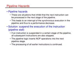
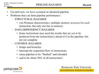
Pipeline Hazards Pipeline hazards • Solution #1 always works: stall, delay & procrastinate! Structural Hazards (i.e. fetching same memory bank) • Solution #2: partition architecture Control Hazards (i.e. branching) • Solution #1: stall! but decreases throughput • Solution #2: guess and back-track • Solution #3: delayed decision: delay branch & fill slot Data Hazards (i.e. register dependencies) • Worst case situation • Solution #2: re-order instructions • Solution #3: forwarding or bypassing: delayed load
Pipeline Datapath and Controlpath Figure 6.30
load inst. Clock 1 Clock 2 Clock 3 Clock 3 WB=11, M=010EX=0001 WB=11M=010 WB=11 PC=4 PC=4+20<<2 Clock 0 PC=4 A=C$1 PC=4+20<<2 MDR=Mem[20+C$1] B=X PC=0 IR= lw $10,20($1) S=20 ALU=20+C$1 Aluout T=$10 D=$10 D=$10 D=0 Figure 6.30
load inst. Clock 1 Clock 2 Clock 3 Clock 3 WB=11, M=010EX=0001 WB=11M=010 WB=11 PC=4 PC=4+20<<2 Clock 0 PC=4 A=C$1 PC=4+20<<2 MDR=Mem[20+C$1] B=X PC=0 IR= lw $10,20($1) S=20 ALU=20+C$1 Aluout T=$10 D=$10 D=$10 D=0 Figure 6.30
Pipeline Datapath and Controlpath Contents of Register 1 = C$1 = 3; C$2=4; C$3=4; C$4=6; C$5=7; C$10=8; … Memory[23]=9; Formats: add $rd,$rs=A,$rt=B; lw $rt=B,@($rs=A) Clock<IF/ID><ID/EX><EX/MEM><MEM/WB> <PC, IR> <PC, A, B, S, Rt, Rd> <PC, Z, ALU, B, R> <MDR, ALU, R> 0<0,?><?,?,?,?,?,?><?,?,?,?,?><?,?,?> 1<4,lw $10,20($1)><0,?,?,?,?,?><?,?,?,?,?><?,?,?> 2<8,sub $11,$2,$3><4,C$13,C$108,20,$10,0><0,?,?,?,?><?,?,?> 3<12,and $12,$4,$5><8,C$24,C$34,X,$3,$11><4+20<<284,0,20+323,8,$10><?,?,?> 4<16,or $13,$6,$7><12,C$46,C$57,X,$5,$12><X,1,4-4=0,4,$11> <Mem[23]9,23,$10> 5<20,add $14,$8,$9><16,C$6 ,C$7,X,$7,$13><X,0,1,7,$12><X,0,$11>
Clock 1: Figure 6.31a PC=4 PC=0 IR=lw $10,20($1)
PC=4 PC=8 IR=lw $10,20($1) IR=sub $11, $2, $3 C PC=4 A=C$1 B=X PC=4 S=20 T=$10 D=0 Figure 6.31b
C C PC=8 PC=4 A=C$2 A=C$1 PC=12 PC=8 B=C$3 B=X S=20 S=X IR=and $12,$4,$5 IR=sub $11, $2, $3 T=$10 T=$3 D=0 D=$11 C PC=4+20<<2 PC=8 ALU=20+C$1 D=$10 Figure 6.32a
C C C Clock 4: Figure 6.32b PC=8 PC=12 C C PC=4+20<<2 A=C$2 A=C$4 PC=12 PC=16 PC=4+20<<2 PC=X B=C$3 B=C$5 MDR=Mem[20+C$1] S=X S=X IR=or $13,$6,$7 IR=and $12,$4,$5 ALU=20+C$1 ALU=C$2-C$3 T=$3 T=$3 ALU D=$10 D=$11 D=$11 D=$12 D=$10 PC=20
Resolved by forwarding At same time: Not a hazard Data Dependencies Data Hazards Forward in time: Not a hazard Data Dependencies: that can be resolved by forwarding Figure 6.36
Data Hazards: arithmetic Forwards in time: Can be resolved At same time: Not a hazard Figure 6.37
8 Clock 1 2 3 4 5 6 7 WB IF ID EX M WB IF ID ID ID EX M Write1st Half Read2nd Half Stall Stall Data Dependencies: no forwarding sub $2,$1,$3 and $12,$2,$5 Suppose every instruction is dependant = 1 + 2 stalls = 3 clocks MIPS = Clock = 500 Mhz = 167 MIPS CPI 3
Data Dependencies: no forwarding A dependant instruction will take = 1 + 2 stalls = 3 clocks An independent instruction will take = 1 + 0 stalls = 1 clocks Suppose 10% of the time the instructions are dependant? Averge instruction time = 10%*3 + 90%*1 = 0.10*3 + 0.90*1 = 1.2 clocks MIPS = Clock = 500 Mhz = 417 MIPS (10% dependency) CPI 1.2 MIPS = Clock = 500 Mhz = 167 MIPS (100% dependency) CPI 3 MIPS = Clock = 500 Mhz = 500 MIPS (0% dependency) CPI 1
Clock 1 2 3 4 5 6 WB IF ID EX M WB IF ID EX M Data Dependencies: with forwarding sub $2,$1,$3 and $12,$2,$5 DetectedData Hazard 1a ID/EX.$rs = EX/M.$rd Suppose every instruction is dependant = 1 + 0 stalls = 1 clock MIPS = Clock = 500 Mhz = 500 MIPS CPI 1
Data Dependencies: Hazard Conditions Example sub $2, $1, $3 sub $rd, $rs, $rt and $12, $2, $5 and $rd, $rs, $rt Destination Source Hazard Type { 1a.1b. ID/EX.$rsID/EX.$rt EX/MEM.$rdest = { 2a.2b. ID/EX.$rsID/EX.$rt MEM/WB.$rdest = Data Hazard Condition occurs whenever a data sourceneeds a previous unavailable result due to a datadestination. Data Hazard Detection is always comparing a destination with a source.
Data Dependencies: Hazard Conditions 1a Data Hazard: EX/MEM.$rd = ID/EX.$rs sub $2, $1, $3 sub $rd, $rs, $rt and $12, $2, $5 and $rd, $rs, $rt 1b Data Hazard: EX/MEM.$rd = ID/EX.$rt sub $2, $1, $3 sub $rd, $rs, $rt and $12, $1, $2 and $rd, $rs, $rt 2a Data Hazard: MEM/WB.$rd = ID/EX.$rs sub $2, $1, $3 sub $rd, $rs, $rt and $12, $1, $5 sub $rd, $rs, $rt or $13, $2, $1 and $rd, $rs, $rt 2b Data Hazard: MEM/WB.$rd = ID/EX.$rt sub $2, $1, $3 sub $rd, $rs, $rt and $12, $1, $5 sub $rd, $rs, $rt or $13, $6, $2 and $rd, $rs, $rt
Data Dependencies: Worst case Data Hazard 1a: EX/MEM.$rd = ID/EX.$rs Data Hazard 1b: EX/MEM.$rd = ID/EX.$rt Data Hazard 2a: MEM/WB.$rd = ID/EX.$rs Data Hazard 2b: MEM/WB.$rd = ID/EX.$rt Data Hazard: sub $2, $1, $3 sub $rd, $rs, $rt and $12, $2,$2 and $rd, $rs,$rt or $13, $2,$2 and $rd, $rs,$rt
Data Dependencies: Hazard Conditions } 2a.2b. ID/EX.$rsID/EX.$rt = MEM/WB.$rdest MEM/WB $rd Hazard Type Source Destination } 1a.1b. ID/EX.$rsID/EX.$rt = EX/MEM.$rdest Pipeline Registers ID/EX EX/MEM $rs $rt $rd $rd
Data Hazards: Loads Backwards in time: Cannot be resolved Forwards in time: Can be resolved At same time: Not a hazard Figure 6.44
Data Hazards: load stalling Stall Figure 6.45
Data Hazards: Hazard detection unit (page 490) Stall Example lw $2, 20($1) lw $rt, addr($rs) and $4, $2,$5 and $rd, $rs,$rt Stall Condition Source Destination } IF/ID.$rsIF/ID.$rt = ID/EX.$rt ID/EX.MemRead=1 No Stall Example: (only need to look at next instruction) lw $2, 20($1) lw $rt, addr($rs) and $4, $1, $5 and $rd, $rs, $rt or $8, $2, $6 or $rd, $rs, $rt
Data Hazards: Hazard detection unit (page 490) No Stall Example: (only need to look at next instruction) lw $2, 20($1) lw $rt, addr($rs) and $4, $1, $5 and $rd, $rs, $rt or $8, $2, $6 or $rd, $rs, $rt Exampleload: assume half of the instructions are immediately followed by an instruction that uses it. What is the average number of clocks for the load? load instruction time: 50%*(1 clock) + 50%*(2 clocks)=1.5
Hazard Detection Unit: when to stall Figure 6.46
Data Dependency Units Forwarding Condition Source Destination } ID/EX.$rsID/EX.$rt = EX/MEM.$rd } ID/EX.$rsID/EX.$rt = MEM/WB.$rd Stall Condition Source Destination } IF/ID.$rsIF/ID.$rt = ID/EX.$rt ID/EX.MemRead=1
Data Dependency Units EX/MEM MEM/WB $rd $rd Stall Condition Source Destination } IF/ID.$rsIF/ID.$rt = ID/EX.$rt ID/EX.MemRead=1 Pipeline Registers Stalling Comparisons Forwarding Comparisons IF/ID ID/EX $rs $rs $rt $rt $rd $rd
Branch Hazards: Soln #1, Stall until Decision made (fig. 6.4) @3C: add $4, $5, $6@40: beq $1, $3, 7 @44: and $12, $2, $5@48: or $13, $6, $2@4C: add $14, $2, $2@50: lw $4, 50($7) Soln #1: Stall until Decision is made Stall Decision made in ID stage: do load
Branch Hazards: Soln #2, Predict until Decision made 8 Clock 1 2 3 4 5 6 7 WB beq $1,$3,7 IF ID EX M Predict false branch and $12, $2, $5 WB IF ID EX M discard “and $12,$2,$5” instruction lw $4, 50($7) WB IF ID EX M Decision made in ID stage: discard & branch
Branch Hazards: Soln #3, Delayed Decision 8 Clock 1 2 3 4 5 6 7 WB beq $1,$3,7 IF ID EX M Move instruction before branch add $4,$6,$6 WB IF ID EX M Do not need to discard instruction lw $4, 50($7) WB IF ID EX M Decision made in ID stage: branch
Branch Hazards: Soln #3, Delayed Decision 8 Clock 1 2 3 4 5 6 7 WB beq $1,$3,7 IF ID EX M and $12, $2, $5 WB IF ID EX M Decision made in ID stage: do branch lw $4, 50($7) WB IF ID EX M
Branch Hazards: Decision made in the ID stage (figure 6.4) 8 Clock 1 2 3 4 5 6 7 WB beq $1,$3,7 IF ID EX M nop WB IF ID EX M No decision yet: insert a nop Decision: do load lw $4, 50($7) WB IF ID EX M
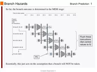
Branch Hazards: Soln #2, Predict until Decision made Branch Decision made in MEM stage: Discard values when wrong prediction Predict false branch Same effect as 3 stalls Figure 6.50
Figure 6.51 Early branch comparison Flush: if wrong prediciton, add nops
Performance load: assume half of the instructions are immediately followed by an instruction that uses it (i.e. data dependency) load instruction time = 50%*(1 clock) + 50%*(2 clocks)=1.5 Jump: assume that jumps always pay 1 full clock cycle delay (stall). Jump instruction time = 2 Branch: the branch delay of misprediction is 1 clock cycle that 25% of the branches are mispredicted. branch time = 75%*(1 clocks) + 25%*(2 clocks) = 1.25
Performance, page 504 Instruction Single-Cycle Multi-CycleClocks PipelineCycles InstructionMix loads 1 5 1.5 23% stores 1 4 1 13% arithmetic 1 4 1 43% branches 1 3 1.25 19% jumps 1 3 2 2% Clockspeed 125 Mhz8 ns 500 Mhz2 ns 500 Mhz2 ns CPI 1 4.02 1.18 = Cycles*Mix MIPS 125 MIPS 125 MIPS 424 MIPS = Clock/CPI
Homework for Wednesday April 5, 2000 1. Convert the RISCEE 1 Architecture into a pipeline Architecture (like Figure 6.30) (showing the number data and control bits).2. Build the control line table (like Figure 6.28) for the RISCEE3 pipeline architecture for RISCEE1 instructions: (addi, subi, load, store, beq, jmp, jal).3. Homework 6.23, p5344. Homework 6.24, p534