Download
1 / 21
210 likes | 391 Vues
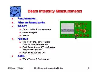
Intensity measurements using TRIC . Juan Carlos Allica On behalf of: M. Andersen, D. Belohrad, L. Jensen, F . Lenardon, A . Monera, L . Søby. Introduction . What is TRIC ( TRansformer Integrator Card)?

E N D
Intensity measurements using TRIC Juan Carlos AllicaOn behalf of: M. Andersen, D. Belohrad, L. Jensen, F. Lenardon, A. Monera, L.Søby
Introduction • What is TRIC (TRansformer Integrator Card)? • TRIC is a VME64x 6U standard card used to measurebeam intensity coming fromFBCTs (Fast Beam Current Transformers) inthe PS complex. • It integrates signals coming from an FBCT using its calibrator as a reference. • Calibration can be either on-line (charges, current) or off-line. • Itoffers differentintegration modes (bunch to bunch, total intensity) with offset suppression. • It is remotely managed by software, a FESA class (internal analyzer).
Introduction Why TRIC? • Automated calibration • Remote setup • Maintainability • Fast upgrade, FPGA remote programming
µController Analog Inputs PLL CLK ADC 212MHz DAC CPLD VME Calibration Outputs FPGA ADC DC-DC 10V TO 200v CALIBRATION DAC Trigger, Inputsand Outputs Hardware TRIC 3.X TRIC 4
x (Beam integra – Offset integra) Measurement principle C x V Q = C x V => N charges Cal = e (Beam integral – Offset integral) N charges Beam = Calibration Concept Calibrator Gate Calibrator Offset Gate Beam Gate Beam Offset Gate Measured Signal Sampling = 5 ns max 212 MHz ADC N charges calibration x (Cal integral – Offset integral)
Measurement process 2 PSB-CPS Timing TRIC Trigger 1. Settings from Expert GUI t 3 And 5 1 2. PSB-CPS trigger Calibrator out t Signal 1 3. Beam signal to TRIC Signal 1 FBCT t 4. Cal signal to FBCT EXPERT GUI SOFTWARE VME BUS Calibrator 5. Cal signal to TRIC Beam and Offset Meas Gate t 6. Intensity calculation Cal and Offset Meas Gate t 4 (Beam integral – Offset integral) N charges Beam = 6 N charges calibration x (Cal integral – Cal Offset integral)
Expert GUI Beam offset Cal. offset Calibration by Charges Beam
Expert GUI • Cal factors improve themeasurement precision • Are calculated by averaging on-line intensity measurements • Cal factors for 0dB, 14dB and 28dB attenuation in order to maximize thedynamic range Measured in Booster and Isolde Cal Factors
Cross calibration • In order to improve the relative precision between theFBCTs we have cross calibrated the TRICs reducing the relative error between them to just TRIC measurement standard deviation (0.25 %) [1], for more info [2]. - The cross calibration procedure starts by sending 1024 calibration pulses from a reference TRIC to the analog inputs of the TRIC been cross-calibrated. - The measurement results are then averaged in each channel and later on averaged with all the other TRICs.The result of the averaging is the number of charges sent by the reference TRIC but with a lower uncertainty.This value is used to calibrate the other TRICs and to reduce the total uncertainty. [1] Lab Measurement withthe TRIC ref’s pulse as input [2] DIPAC 2011, Upgrade of the PCB/CPS Fast Intensity Measurements
Cross calibration 1024 measurements for each card
Cross calibrationset up This setup is repeated for all the TRICs resultingin a calibrationconstant that gives us the deviation for each TRICin respect tothe TRICs’average. • Process starts with a C program “testric”. • TRIC ref sends a calibration pulse whichsimulates thebeam. • Signal is received onthe TRIC DUT for both channels. • TRIC Under Test sends its calibration pulse. • Sends measurement results via VME. • The program “testric” saves the data and repeats the process 1024 times to have the average value of the measurement; all the data is stored in one file.
Measurements with acalibrationconstant Operative Under Test DCCT User : CNGS 2011-10-19 00:00:04.300 To 2011-10-19 01:48:13.900
Measurements with a calibrationconstant User : CNGS 2011-10-19 00:00:04.300 To 2011-10-19 01:48:13.900 100 99 98 97 96 95 94 93 92 91 FBCT-DCCT transfer function without Cal constant FBCT-DCCT transfer function after Cal constant F16.BCT: difference between non cross-cal and cross-cal is 1% when comparing with DCCT. 13
TRIC deployment Operative Under Test 04/11/2011
TRIC deployment • TRICs currently installed Outlook
Outlook • Introduce certain hardware modifications to reduce the thermal and electromagnetic noise (new DC-DC converter in new version TRIC 4). • Replace the old FBCTs (some are more than 30 years old) in order to have a standard setTRIC + FBCT fortheintensity measurements.
Conclusions • TRIC has become the new standard forthe beam intensity measurement in the PS complex. • TRIC 4 prototype manufacturing and 30 boardsbuch intended for 1st Q 2012. • 17 units currently installed in total, 30 units expected to be installed for LINAC3, LINAC4, AD and LEIR.
ADC Analog Devices AD9430 Resolution Q = FSR/N => 1.5/2^10.6 Q = 966.43 µV Differential Non Linearity Clock Oscillator Integral Non Linearity Model CCPD-034 is a 162.000MHz to 250.000MHz LVPECL Phase Jitter: 12kHz~80MHz 0.5ps typ., 1psRMS max
Cross correlation FBCT Before Cal constant