Download
1 / 21
210 likes | 303 Vues
Study of Secondary Emission Enhanced Photoinjector. Xiangyun Chang 1 , Ilan Ben-Zvi 1,2 , Andrew Burrill 1 , Peter D. Johnson 2 Jörg Kewisch 1 Triveni S. Rao 3 and YongXiang Zhao 2 Collider-Accelerator Department 1 , Physics Department 2 , Instrumentation Division 3

E N D
Study of Secondary Emission Enhanced Photoinjector Xiangyun Chang1, Ilan Ben-Zvi1,2, Andrew Burrill1, Peter D. Johnson2 Jörg Kewisch1 Triveni S. Rao3 and YongXiang Zhao2 Collider-Accelerator Department1, Physics Department2, Instrumentation Division3 Brookhaven National Laboratory Upton NY 11973 USA
Introduction Schematic diagram of a secondary emission enhanced photoinjector
The advantages of the Secondary Emission Enhanced Photoinjector • 1. Reduction of the number of primary electrons by the large SEY, i.e. a very low laser power requirement in the photocathode producing the primaries. • 2. Protection of the cathode from possible contamination from the gun, allowing the use of large quantum efficiency but sensitive cathodes. • 3. Protection of the gun from possible contamination by the cathode, allowing the use of superconducting gun cavities. • 4. Production of high average currents, up to ampere class. • 5. Expected long lifetime
Design considerations • The metal layer • The choice of material. • One would like to use material which has high electrical conductivity (σ) to reduce the resistance of the film. • On the other hand one would like use material which big long Continuous Slowing Down Approximation (CSDA) range parameter RCSDA to reduce the energy loss in the metal film • The Al is the best choice.
RF penetration of the Al film for 700MHz MW It is proven that the RF penetration of the metal film is very small for our application. So, Al film not only carries out the replenishment current but also the large RF current. This makes the thicker Al film more important.
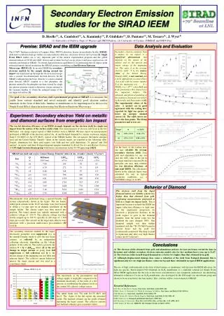
The secondary electron yield (SEY) SEY measurement for reflection mode A. Shih, J. Yater, P. Pehrsson, J. Butler, C. Hor, and R. Abrams J. Appl. Phys., Vol. 82, No. 4, 15 August 1997 It is expected that almost all the secondary electrons produced would come out from the diamond for our transmission mode. We will assume a conservative SEY value of 300 at 4keV for our application.
The thickness of diamond window • One would like to use thicker diamond to improve the thermal conduction of the window. • On the other hand, for our RF application the diamond thickness is limited due to the allowed transmission time for the secondary electrons and the limited electron drifting velocity in diamond. • The allowed transmission time is 120~200ps for our case. • The drift velocity is
Diamond has the highest thermal conductivity. The thermal conductivity is determined by the grain size, boundary, umklapp process and impurity of the film. • Diamond thermal conductivity
. Grain size and surface roughness of our 30μm thick diamond sample
The impurity problem • Impurities: Boron (p-type), Nitrogen (n-type), Hydrogen (n-type), Phosphorus (n-type), Lithium (n-type) and Sodium (n-type). • Heating problem: • Free electrons on diamond conduction band (Nitrogen doping). Under the strong RF field, it will behave the same way like the secondary electrons. So, not only produces extra heat but also the background current and back-bombardment. • If the holes on the valence band (Boron doping) is big, it will only produce the extra heat. • Field shielding problem: • If the concentration of free electrons or holes is too high, it can be thought as a bad quality conductor. So, the RF field attenuates inside diamond surface and then affects the drift velocity of the secondary electron
Limits on impurities: • The concentration of the free electrons or holes should be well below the secondary electron density in diamond. For RHIC cooling, charge/bunch=20nC, the density is about: • The Hydrogen, Phosphorus and other alkali elements impurities form strong chemical bonds with C with no free electron. So, this impurities are not important . • Nitrogen:1ppm or more ( ) The activation energy can be 1.7eV or more. The portion exited to conduction band by thermal at T=500K: • Boron: • Boron doping concentration can be easily less than
Diamond temperature • RHIC e-cooling project: Charge=20nC/bunch Repetition frequency=9.4MHz Radius R>10mm Primary electron energy EPri=10keV Diamond thickness rDmd=30μm Al thickness tAl=800nm Peak RF field on cathode E0=15MV/m SEY=300 Temperature on diamond edge Tedge=80K Primary electron pulse length PlsPri=10deg
Energy Recovery Linac (ERL) project in BNLCharge=1.42nC/bunchRepetition frequency=703MHzRadius R~5mmPrimary electron energy EPri=10keVDiamond thickness rDmd=30μmAl thickness tAl=800nmPeak RF field on cathode E0=15MV/mSEY=300Temperature on diamond edge Tedge=80KPrimary electron pulse length PlsPri=10deg
Secondary electron beam quality • Bunch broadening Drift velocity is saturated if E>2MV/m, the broadening is determined by the straggling distance of primary electron in diamond: This is equivalent to a 2.6ps long laser pulse • Limit on charge density For RHIC cooling example with R=12.5mm, Q<< 65nC For ERL example with R=5mm, Q<<10nC
Conclusion • The study and calculations show great feasibility of Secondary Emission Enhanced Photoinjector. • The new approach has many advantages.