Download
1 / 11
110 likes | 245 Vues
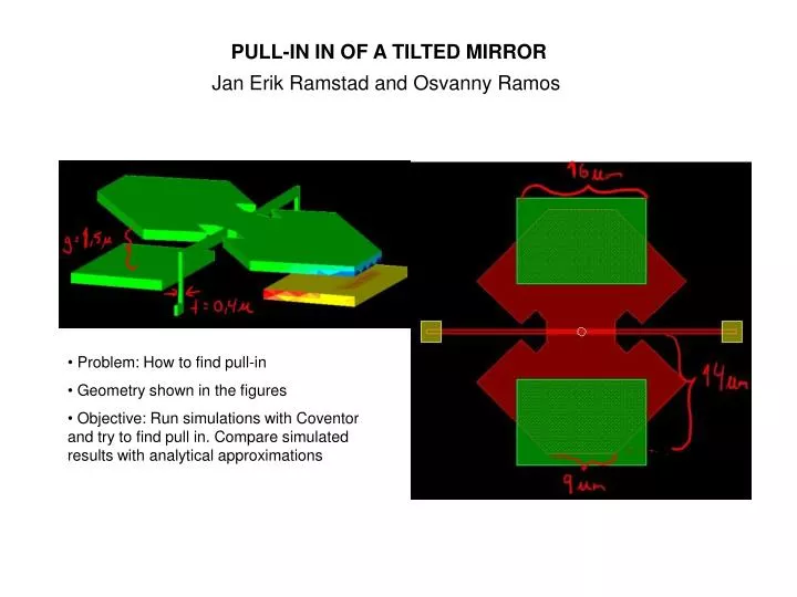
PULL-IN IN OF A TILTED MIRROR. Jan Erik Ramstad and Osvanny Ramos. Problem: How to find pull-in Geometry shown in the figures Objective: Run simulations with Coventor and try to find pull in. Compare simulated results with analytical approximations. CoventorWare Analyzer. Mirror Design.

E N D
PULL-IN IN OF A TILTED MIRROR Jan Erik Ramstad and Osvanny Ramos • Problem: How to find pull-in • Geometry shown in the figures • Objective: Run simulations with Coventor and try to find pull in. Compare simulated results with analytical approximations
CoventorWare Analyzer Mirror Design • Before simulations, we wanted to find formulas to compare simulations with. • The parallell plate capacitor analogy • The parallell plate capacitor formulas are analog to how the mirror actuation works. • Mechanical force must be equal to electrical force to have equilibrium • Storing of energy in capacitor • Energy formula used to derive electrical force
- e e 2 2 AV AV = > F k elec 2 3 2 2 g g CoventorWare Analyzer Mirror Design The parallell plate capacitor analogy (continued) • Using parallell plate capacitor formula with F gives • Fmech comes from the spring and gives net force • By derivating net force we can find an expression to find stable and unstable equilibrium. • The calculated k formula will give us the pull in voltage and pull in gap size if inserted in Fnet formula
CoventorWare Analyzer Mirror Design Derivation of formulas for the mirror design • By using parallell plate capacitor analogy formulas we can find formulas for mirror design • The forces are analogous with torque where distance x is now replaced with Θ Tilted angle • Formulas for torque calculations shown below
CoventorWare Analyzer Mirror Design Derivation of formulas for the mirror design (continued) • Hornbecks analysis computes torque directly treating tilted plate as parallell plate. • Eletric torque formula is analogous to electric force: ...and analyzing the stability of the equilibrium Difficult analytically!
CoventorWare Analyzer Mirror Design Alternative analytical solution: • Using Hornbecks electrical torque formula will be difficult to calculate. By running simulation, capacitance and tilt values can be achieved • Using the values from simulation can be used to make a graph. This graph is a result of normalized capacitance and angle • Using the same formulas as earlier, but now with the new formula for capacitance is used to find electric torque: • General formula from graph can be of the following third polynomial formula; • From mechanical torque formula, we can find the spring constant (stiffness of ”hinge”)
CoventorWare Analyzer Mirror Design Alternative analytical solution (continued): • The spring constant formula has our variable Θ. By rearranging this formula, Θ is a second degree polynomial, which must be solved for positive roots: • The root expression must be positive for a stable solution. This will give us a formula for pull in voltage • Now that we had a formula to calculate pull in voltage, we attempted to run Coventor simulations
0.4 CoventorWare Analyzer Graph of normalized capacitance vs angle Mirror Design 47V Original geometry: 1.5 40V 20V 20V Graph: Red line is analytical approximationDotted points are measured results from Coventor 40V • Only one electrode has applied voltage • No exaggeration is used • Mesh is 0,4 micrometer, equal to hinge thicknessMesh was not changed when changing geometry parameters. • Results: 47V
CoventorWare Analyzer Graph of normalized capacitance vs angle 20V Varying k by reducing hinge thickness 0.2 1.5 15V 10V 10V 15V Graph: Red line is analytical approximationDotted points are measured results from Coventor • Reducing hinge thickness resulted in: • Decreased k • Decreased pull in voltage 20V
0.2 CoventorWare Analyzer Graph of normalized capacitance vs angle Varying the distance from the electrodes 35V 2.5 20V 30V 20V 30V Graph: Red line is analytical approximationDotted points are measured results from Coventor • Increasing gap size resulted in: • Small deacrease in k • Increased pull in voltage 35V Pull in not found
CONCLUSIONS - We didn’t find pull-in regime in our simulations. - Instead of the parallel capacitor where , in the tilted capacitor the pull-in depends on the characteristics of the system. - The fitting of the curve was not easy. Our measured results were very sensitive to how the curve looked. The curve might have something different than a third degree polynomial dependency on the angle. - Nonlinearities of the forces not taken into account for the analytic calculations. • Problems with the solution when this happens -> • Suggestion to find pull in : • Increase hinge thickness • Decrease mesh size 50 V