Download
1 / 28
280 likes | 736 Vues
Chapter 6. InterVLAN Routing. Objectives. Upon completion of this chapter, you will be able to perform the following tasks: Identify the network devices required to effect interVLAN routing Configure a default gateway to ensure network reachability

E N D
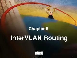
Chapter 6 InterVLAN Routing
Objectives • Upon completion of this chapter, you will be able to perform the following tasks: • Identify the network devices required to effect interVLAN routing • Configure a default gateway to ensure networkreachability • Configure a route processor to facilitateinterVLAN routing
InterVLAN Routing • In this chapter, we discuss the following topics: • InterVLAN routing issues • Distribution layer topology • Configuring interVLAN routing
InterVLAN Routing • In this section we discuss the following topics: • InterVLAN Routing Issues • Isolated Collision Domains • Finding the Route • Supporting Multiple VLAN traffic • Distribution Layer Topology • Configuring InterVLAN Routing
Problem: Isolated Broadcast Domains 172.16.20.4 VLAN20 VLAN10 VLAN30 • Because of their nature, VLANs inhibit communication between VLANs
Solution: Routing Between VLANs 172.16.20.4 VLAN20 VLAN10 VLAN30 • Communications between VLANs require a routing processor
Problem: Finding the Route I need to send this packet to 172.16.20.4. That address is not on my local segment. VLAN20 VLAN10 172.16.10.3 172.16.20.4 Network 172.16.20.0 Network 172.16.10.0 • InterVLAN communications introduce the problem of where end-user stations send nonlocal packets
Solution: Defining a Default Gateway I will send the packet to my default router. VLAN20 VLAN10 172.16.10.3 172.16.20.4 Network172.16.10.0 Network 172.16.20.0 I know where network 172.16.20.0 is! • End-user stations send nonlocal packets to a default router
Problem: Supporting Multiple VLAN Traffic I need information from File Server A. I need information from File Server A. I need information from File Server A. I have three distinct streams of traffic destined for the same place! ? ? ? ? File Server A172.16.3.127 VLAN30 VLAN20 VLAN10 • Multiple VLANs interfacing with a single route processor require multiple connections or VLAN trunking
Solution: Multiple Links VLAN10 VLAN20 VLAN30 VLAN60 • The router can support a separate interface for each VLAN
Solution: Inter-Switch Link VLAN10 VLAN20 VLAN30 VLAN60 Eth 3/0.1 3/0.2 3/0.3 Eth 3/1.1 3/1.2 3/1.3 • The router can support a single ISL link for multiple VLANs
InterVLAN Routing • In this section we discuss the following topics: • InterVLAN Routing Fundamentals • Distribution Switch Topology • External Route Processors • Internal Route Processors • Configuring InterVLAN Routing
Distribution Layer Route Processors Distribution Layer • The distribution-layer device is a combination of a high-end switch and a route processor
External Route Processor VLAN41 Network 172.16.41.3 VLAN41 Network 172.16.41.4 Switch A Switch B Switch C VLAN42 Network 172.16.42.5 • An external Cisco high-end router and a Catalyst 5000 switch with an NFFC or NFFCII • Connected by multiple Ethernet connections or an ISL link
Internal Route Processors VLAN41 Network 172.16.41.3 VLAN41 Network 172.16.41.4 VLAN42 Network 172.16.42.5 • Multilayer switches integrate Layer 2 and Layer 3 functionality in a single box
Internal Route Processors (cont.) RSFC • RSFC is a daughter card on the Supervisor Engine IIG and IIIG RSM • RSM can reside in slots 2 through 12 of a Catalyst 5000 switch
InterVLAN Routing • In this section we discuss the following topics: • InterVLAN Routing Fundamentals • Distribution Layer Topology • Configuring InterVLAN Routing • Locating and accessing the routeprocessor • Configuring an interface • Defining a default gateway • Testing the link
Locating the Route Processor Switch (enable) show module Mod Module-Name Ports Module-Type Model Serial-Num Status --- ------------- ----- --------------------- --------- --------- ------- 1 0 Supervisor III WS-X5530 010821493 ok 2 24 10/100BaseTX Ethernet WS-X5225R 012145458 ok 3 1 Route Switch WS-X5302 006825295 ok • Specifying a particular module number displays information on that module • Not specifying a module number displays information on all modules installed in the system
Accessing the Route Processor Switch (enable) session 3 • Eliminates the need to connect a terminal directly to the RSM console port
Identifying the Route Processor Router(config)#hostnameRSM143 Router(config)exit RSM143# • The hostname uniquely identifies each route processor within the network
Enabling an IP Routing Protocol RSM141(config)#ip routing RSM141(config)#router igrp 1 RSM141(config-router)#network 172.16.0.0 172.16.10.0 172.16.30.0 Network 172.16.0.0 172.16.20.0 • Routing protocols determine optimal paths through the network and transport information across these paths
Configuring an VLAN Interface on an Internal Route Processor RTR144(config)#interface vlan41 RTR144(config-if)#ip address 172.16.10.3 255.255.255.0 RTR144(config-if)#exit RTR144(config)#interface vlan42 RTR144(config-if)#ip address 172.16.20.3 255.255.255.0 RTR144(config-if)#exit • The internal route processor automatically encapsulates packets using ISL • Initial configuration requires a no shutdown command
Configuring an VLAN Interface on an External Route Processor Port Slot Subinterface Number RSM144(config)#interface fastethernet 0/1.1 RSM144(config-if)#encapsulation isl 10 RSM144(config-if)#ip address 172.16.10.3 255.255.255.0 RSM144(config-if)#exit RSM144(config)#interface fastethernet 0/1.2 RSM144(config-if)#encapsulation isl 20 RSM144(config-if)#ip address 172.16.20.3 255.255.255.0 RSM144(config-if)#exit Encapsulation Type and VLAN Number Interface FA 0/1 Subinterface 0/1.1 VLAN10 VLAN20 Interface FA 0/1 Subinterface 0/1.2 • Subinterfaces allow for routing multiple data streams through a single physical interface • Initial configuration requires a no shutdown command
Defining a Default Gateway Default Gateway 172.16.1.163 ASW31#config t Enter configuration commands, one per line. End with CNTL/Z ASW31(config)#ip default-gateway 172.16.1.163 VLAN40 VLAN30 172.16.1.163 Default Gateway 172.16.1.163 ASW41#config t Enter configuration commands, one per line. End with CNTL/Z ASW41(config)#ip default-gateway 172.16.1.163 • Defining a default gateway facilitates interVLAN communications
Testing the Link PC41#ping 172.16.10.3 Sending 5, 100-byte ICMP Echos to 172.16.10.3, time out is 2 seconds: !!!!! Success rate is 100 percent (5/5), round-trip min/avg/max 0/0/0/ ms • The ping command tests connectivity to remote hosts
Laboratory Exercise: Visual Objective Switch Block X VLAN x1 VLAN x2 VLAN x3 VLAN x4
Summary • InterVlan routing is a requirement to enable communication between devices in separate VLANs. • Most devices are configured with the IP address of a default router to which all non-local network packets are sent. • The Inter-Switch Link (ISL) protocol is used to facilitate multiple VLAN traffic over a single link. • The distribution layer routing processor can be an internal or external router/switch topology.
Review • List at least two problems that can impede communications between VLANs, and identify a solution for each problem. • Identify at least two Cisco platform solutions for an internal route processor topology at the distribution layer. • Compare and contrast the steps used to configure an interface on an RSM and an ISL link on an external router.