Download
1 / 57
570 likes | 574 Vues
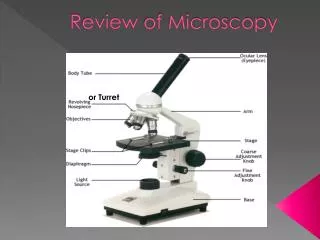
Publication Project and Microscopy Review. Imaging, Robotics, & Intelligent Systems Laboratory University of Tennessee Chris Kammerud Summer 2004. Outline. Instrumentation/Publication Project Review other’s previous work Revisements to paper Put Viz-Tek back together Implementation

E N D
Publication Project and Microscopy Review Imaging, Robotics, & Intelligent Systems Laboratory University of Tennessee Chris Kammerud Summer 2004
Outline • Instrumentation/Publication Project • Review other’s previous work • Revisements to paper • Put Viz-Tek back together • Implementation • Reviewed Matt’s previous work • Collected Information on microscopes in SERF Lab • Collected data with Matt • Mosaic Data • Survey of Nano-scale Computer Vision • Enhancment methods • 3D reconstruction systems • Survey of Nano-scale Instruments • Microscope Systems • Nano-Stages • Software Packages • Conclusions and Future Work
Instrumentation/Publication Objectives • Revise report based on suggestions and with more references to previous work • Put Viz-Tek back together
Others Work in Luggage Simulation • Alstec: Airport Technology – Baggage Systems Simulation Tests. [Als04] • Airport Luggage Inspection Simulation with Force Feedback. [Har04] • EDTECH AIR Security Simulator. [Edt03] • Explosives detection systems (EDS) for aviation security. [Sin03] • Innovations, Inc. TIP – Threat Image Projection. [TIP04] • Research Projects – Airport Luggage Handling, Airport simulation library. [Val04]
Revising paper • Included more references to work mentioned on previous slide • Focus on contributions and differences with work I did compared to the work of others • Much work was done, ([Als04] and [Val04] ) with high level simulation, i.e. simulating the flow of passengers through security with models of luggage screening. My research is at a lower level, building simulated models of packed luggage • Work has also been done in simulating x-rays of luggage ([TIP04] and [Edt03] ). My research was in developing virtual models of luggage and does not use or need previous x-rays of real luggage
Results • A revised paper was created with new sections on motivation, contribution, and a few others. • Previous work was researched and read to determine the contribution of my work
Plan for Inst/Pub Project • Further changes will be made according to the suggestions received in the past days • Inquiries into when and if Viz-Tek system can be reassembled • Depending on amount of work needed to be done with report, refinements could be made to the luggage simulation script in 3DSM.
Implementation Objectives • Familiarize self with microscopes in SERF • Review Matt and Sherry’s work • Collect own data • Expand on data by mosaicing
Review of Matt and Sherry’s work • Matt’s work looked at includes • “The State of the Art of Range Imaging” [Sch02] • “Image Acquisition and 3D Model Reconstruction of Biomedical Specimens” [Sch03] • “SEM Preparation” section of master thesis paper he’s working on • Sherry’s work looked at • “Microscopic Scanning” [Ali04] • Got book on Microfabrication from her
Familiarization with Microscopes • Went with Matt to learn SEM • Learned how to prepare samples • Used SEM to collect images
Data Collected • Collected Images of Liver Cell using SEM • Magnification @ 1.5k • 80 nm square pixels
Data Collected to Mosaic Magnification at 6000x, pixel size 20 nm square
Mosaiced Data Mosaiced Image Size 2073 x 1057
Comparison of detail Mag 1.5k Mag 6k Enlarged versions of picture above
Survey of Nano-Scale CV Methods Objectives • Review of algorithms for nano-scale devices • Review methods and systems for 3D reconstruction
Enhancement algorithms • “Noise adaptive channel smoothing for low-dose images” [Sch et al03] • “Scaling-index method as an image processing tool in scanning-probe microscopy ” [Jam et al01]
Noise adaptive channel smoothing • Nano-scale images have different noise characteristics than camera based, Poisson vs Gaussian • Channel smoothing • Each pixel value has N vector weight(N channels) attached to it • Channels are smoothed individually • Image is reconstructed from smoothed channels
Channel Smoothing cont • Adapting to Poisson • Low-intensity images with Poisson noise, the noise variance increases at increased gray-level values • Smoothing is done per channel with Gaussian function, higher channels(higher gray-levels) are smoothed with Gaussian of higher variance Channel smoothing information and images from [Sch et al03]
Scaling Index Method • Method used to extract structural information from arbitrary data sets • Examining increase in points encircled by spheres of growing radii gives a scaling index for a specific pixel/point [Jam et al01]
Scaling Index Method • Results shown for images from light microscope image(top) and AFM image(bottom) [Jam et al01]
Scaling Index Method • Scaling index images, very similar despite their very different origins. • Scaling index method could be useful in registering images from different microscopes Light Microscope AFM Microscope [Jam et al01]
3D Methods • Methods for the alignment of images • Micro Axial Alignment • Common line correlation • AFM image alignment • Methods for reconstruction from multiple views for different microscopy technologies • X-ray microscopes • Optical Profiling • AFM • Electron microscopy
Image Alignment • Majority of 3D reconstruction algorithms use multiple views taken of an object • Multiple views need to be aligned • Image alignment also necessary when measuring specimen surface change caused by chemical or other effect
Micro-Axial Alignment • “Precise 3D Image Alignment in Micro-axial Tomography ” [Mat et al03] • Particles are arranged on a glass fibre • Feature based-alignment: centres of gravity used • Bipartite graphy
Common line correlation • “Strul - a Method for 3D Alignment of Single-Particle Projections Based on Commmon Line Correlatin in Fourier Space ” [Lin01] • 3D alignment done of single particles • Two 2D Fourier transforms of projection through same 3D volume will share one line through 3D Fourier transform • This line can be used to determine relative orientation
Common line correlation • 2179 particles were imaged at two tilts • 3D reconstruction was done, images (a) and (b) show a top and side view respectively • From these two classifications 400 particles were randomly chosen and used to form a 3D reconstruction (c) • Projections slicing the 3D model along different angles were used as the model set that Strul rotationally aligned all 2179 particles with. The rotation angles found to give the highest correlation were used to form a 3D model (d)
Aligning AFM Images • [Rom et al00] “Alignment of AFM images using an iterative mathematical procedure” • AFM microscopes used to study chemical or other processes that occur over time • Surface area of a specimen needs to be imaged at least twice • AFM experiences vertical and lateral drift, as well as rotational drift • Need to align AFM images
Aligning AFM Images • Algorithm forms three square regions taken in the two images as references for alignment • Cross-correlation between regions is maximized with center points as references (a) And (c) before corrosion, (b) and (d) after corrosion, (c) and (d) aligned images
3D X-ray Diffraction Microscopy • “High Resolution 3D X-ray Diffraction Microscopy” [Jia et al02] • Microscopy combining coherent x-ray diffraction with the oversampling phasing method • X-rays probe deeper into specimen than electrons but are harder to focus • Resolution from this paper’s method is 8 nm for 2D image and 50 nm for the 3D reconstruction
3D X-ray Diffraction Microscopy, 2D results Electron scan X-ray scan, lower layer information visible [Jia et al02]
3D X-ray Diffraction Microscopy, 3D results [Jia et al02]
3-D of MEMS • “Innovative Metrology Method for the 3-Dimensional Measurements of MEMS” [Wol et al04] • Phase Shift Inteferometry • Known wavefront interfering with unknown waves reflected from specimen • Paper presents method without moving mirror • Measurement of certified step hight within 0.4 nm
3-D of MEMS, Results Silicon Pit Cantilever [Wol et al04]
3D Modeling from AFM • “3D Modeling from AFM measurements” [JosHug01] • Similar to range scanning of models we do at IRIS • AFM measurements are taken with the sample at different orientations to the scanner • These models are combine into a more complete 3D model
3D Modeling from AFM, Block Diagram Block diagram of system proposed, [JosHug01]
3D Modeling from AFM (Results) Two views of quartz particle model combined [JosHug01]
Electron Microscopy • [HemSch97] "Digital Microphotogrammetry— Determination of the Topography of Microstructures by Scanning Electron Microscope" • Reconstructing 3D images from series of tilted views from an SEM microscope • Matt Schultz has used this algorithm for his efforts in creating 3D models from the SEM. • The algorithm takes into account parallel projection, an attribute of SEM imaging.
Electron Microscopy • The orientation parameters, translation and rotation, estimated from views of a sample at different tilting angles • Matching of points must be done between the images taken. • The paper presents correlation techniques using area and feature based matching • Image from area-based processing on right
Plans on CV Survey • Continue looking at papers and new research • Write into report as collect
Survey of Nano-Scale Instrument Objectives • Collect information on commercially available products • Microscopes • TEM • SEM • AFM • NSOM/SNOM • Accessories • Nano-Stages • Software
Commercial Microscopes • Types of Microscopes • Standard Optical Light • Confocal • TEM • SEM • AFM • NSOM/SNOM • The bottom 4 are best able to image with resolutions < 100 nm
TEM • Similar to conventional light microscope • Electron beam passes through thin slice of sample • Electromagnetic lenses focus and magnify
JEM-3000F FasTEM • 100-300 kV operating voltage • Resolution 0.17 nm http://www.jeol.com/
SEM • Surface of sample is excited by electron beam • Electrons from the surface that scatter are collected and focused
Hitachi S-5200 UHR In-lens FE-SEM • 0.5 nm resolution at 30 kV • 1.8 nm at 1 kV • Maximum magnification 2,000,000 http://www.hitachi-hta.com
Jeol JSM-7700F • 0.6 nm at 5 kV • 1 nm at 1 kV • 1 nm at 15kV • Maximum Magnification 2,000,000 [Leo04]
AFM • Sample is raster scanned by a probe • Major Modes of Operation • Contact • Probe touches surface • Deflection of probe measured • Non-Contact • Probe vibrates near surface • Vibration amplitude changes by proximity of surface • Tapping • Probe vibrates and taps surface • Combination of contact and non-contact
Aslyum MFP-3D • Recently added to SERF • Noise level in Z < 0.2 nm, and < 0.4 nm for X and Y directions [Asy04]
NSOM/SNOM • SPM technology, light passed through tiny aperture • Four modes, transmission, reflection, collection, illumination [NSO04]
Nanonics Image 30 nm gold balls Nanonics NSOM in upright microscope Images from http://www.nanonics.co.il/main/prod_item.php?ln=en&item_id=80&cat=5&sub_cat=22