Download
1 / 44
470 likes | 1.21k Vues
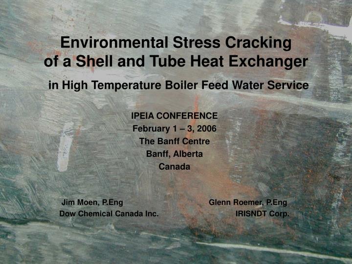
Environmental Stress Cracking of a Shell and Tube Heat Exchanger in High Temperature Boiler Feed Water Service. IPEIA CONFERENCE February 1 – 3, 2006 The Banff Centre Banff, Alberta Canada Jim Moen, P.Eng Glenn Roemer, P.Eng

E N D
Environmental Stress Cracking of a Shell and Tube Heat Exchangerin High Temperature Boiler Feed Water Service IPEIA CONFERENCE February 1 – 3, 2006 The Banff Centre Banff, Alberta Canada Jim Moen, P.Eng Glenn Roemer, P.Eng Dow Chemical Canada Inc. IRISNDT Corp.
The Problem • Large vertical heat exchanger developed through wall leaks at a shell to tubesheet butt-weld. • Initial cracking occurred after 3 years in service. • Other cracking developed over the next 5 years and eventually detected and repaired. • In September 2003, inspections conducted during a scheduled shutdown of the heat exchanger revealed extensive transverse and longitudinal cracking. • Cracking affected virtually all of the shell-side weld seams as well as 31 of the 37 nozzle-to-shell welds. • Down for a total of 131 days while a thorough investigation and extensive repairs were undertaken. • The shell-side environment - high temperature (465ºF), treated boiler feed
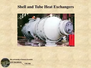
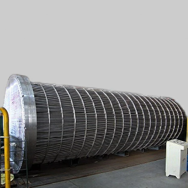
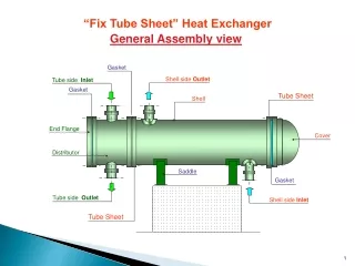
Equipment Description • Vertical shell and tube heat exchanger. • Heavy walled • Large diameter • Quenched and tempered, high yield, alloy steel • Operated in the as-welded condition • Shell-side contains treated boiler feed water at ~465F and ~485 psig • Tube-side contains a chemical process reaction stream
Cracking History • Initial through-wall cracking was detected after 3 years operation. • Cracking was transverse (across the weld). • After many years without detectable crack growth more leaks were found (after 8 years operation). • One year later more cracking was detected. • Extensive fitness-for-service and weld repairs were carried to all seams and most nozzle welds.
Environment • The shell side contains treated boiler feed water at ~465F and ~485 psig. • Organics in the water during spring run-off necessitate caustic additions to neutralise organic acids. • The water chemistry is consistent with typical industrial boiler water standards. • The table below contains the shell side water chemistry data collected over a 3 week period in 2003 from the cooling water separator downstream of the heat exchanger. The specified boiler water control limits are also shown.
Investigation • Core samples removed during each repair • Nozzles and welds removed • Weld seam samples removed • Metallurgical analysis • Electrochemical testing • Difference analysis • Residual stress measurements • Residual stress modeling
Core Samples • Core samples were bored from crack locations during each repair. • Approximately ~1/4” diameter and full thickness. • Used for metallurgical evaluation.
Top Sample HAZ Center Sample SMAW E11018-M SAW F11A6-ECM-M2 HAZ Bottom Sample Base Material “HY80” Outside Surface Inside Surface Core Locations
Sample was split open along this crack CS 15.5b: Mounted Planar Section; red arrows indicate polished surface. CS 15.5c: Remaining piece left as received CS 15.5a: Mounted Cross Section; blue arrows indicate polished surface Core sample Core sample CS 15.5 showing the crack and sample identification
Nozzle cracks Colour contrast magnetic particle inspection (MPI) image of a nozzle to shell weld external surface showing through wall cracking
Nozzle cracks Colour contrast magnetic particle inspection (MPI) image of a nozzle to shell weld internal surface showing cracking
Deposited Weld Metal Outside Surface Tensile Sample Locations Base Material “HY80” Inside Surface Longitudinal Cap Sample Location Sample Locations – Long Seam
Sample was split open along this crack CS 15.5b: Mounted Planar Section; red arrows indicate polished surface. CS 15.5c: Remaining piece left as received CS 15.5a: Mounted Cross Section; blue arrows indicate polished surface Core sample Core sample CS 15.5 showing the crack and sample identification
Core section with ID crack The polished LS 8 longitudinal cross-section showing cracks initiating on the heat exchanger inside surface. The deposited weld metal is clearly shown
253 249 262 258 258 276 285 276 330 336 356 343 336 336 330 350 285 276 280 296 285 290 285 296 312 312 Cross section with crack/HAZ Core sample CS 15.5 with Vickers microhardness (HV 0.5/15) measurements around the crack
Pitting/Scale The heat exchanger inside surface represented by core sample LS 8 The polished BS 13.75 inside surface tab showing the crack and pitting,2% Nital etch
Crack Metallography CS 15b microstructure of branched cracking off a large main crack, 2% Nital etch
Crack Metallography CS 15.5b microstructure of the deposited weld metal cracking, 2% Nital etch
Crack Metallography Secondary electron (SE) image of the grain boundary cracking and scale on CS 8PH
Crack Metallography • Initial cracks were believed to be welding related defects. • The cracks examined in the core samples taken in 2002 and 2003 are a result of environmental stress cracking. • The results consistent with this conclusion are that the cracks: • Are only present in the deposited weld metal and HAZ. These zones typically have the highest stresses from welding. • Propagated from the inside to outside surface indicating the shell side high temperature water is a major factor. • Are located in multiple shell side weld locations throughout the heat exchanger.
Crack Metallography • … the cracks: • Typically initiate from pits. • Are multiple, branched, and are inter-dendritic and trans-dendritic, most of which appears to follow prior austenite grain boundaries. • These features are typical of environmental stress cracking in high temperature water (ref. 1). The mixed mode cracking is likely related to high joint and residual welding stresses. • Have a thin scale containing mainly Fe and O, typical of a corrosion related process.
Difference Analysis • A difference analysis to understand why this heat exchanger has developed cracking and not the associated piping, or other vessels was completed. • Smaller heat exchanger in parallel process • Downstream process vessel • Interconnecting piping
Environmental Cracking • Cracking appears to be environmental stress cracking. • For environmental stress cracking the following factors must be present: • A susceptible material. • Tensile stresses ; these can be applied, residual, thermal, or a combination. • An environment that will cause cracking.
Material • Shell is constructed of ASME SA543, Type B, Class 1. • Nozzles and tubesheets were constructed of ASME SA508, Grade 4N. • Both are ASME variations of a medium strength, high toughness, alloy steel commonly known as HY80; this designation is referred to throughout the paper. • The chemical composition differences between HY80 and the ASME grades are shown in the next table. • Welding was performed using 110 ksi filler metals • SMAW E11018-M • SAW F11A6-ECM-M2
Stress • The lower tubesheet-to-shell weld is the highest stressed circumferential weld according to data presented in the fabricator’s stress analysis report. • The service stresses were calculated to be 92 ksi on start-up and 88 ksi under normal operation. • Other stresses relevant to this discussion are the deposited weld metal and base material yield strengths: • The minimum tensile yield strength (TYS) of the deposited weld metal is ~100 ksi • The minimum specified TYS of the shell material is 85 ksi. • Welding residual stresses, at or near the deposited weld metal, can be as high as the yield strength (ref. 2, 3). • Post weld heat-treatment (PWHT) is commonly used to reduce these residual stresses. • ASME Code warns about temper embrittlement if the optional PWHT is performed incorrectly.
Stress Analysis - FEA • FEA was performed to better estimate the residual stress state for the fitness-for-service analysis (ref. 4). • Modeled the deposition of each welding pass to calculate the actual stress developed but the welding solidification and heating cycles. • Simplified to use only 16 passes. • Used the fabricator’s welding parameters. • More complicated models have proven that the simplification is quite accurate.
Stress • Residual stress measurements were made using the hole-drilling method on the outside surface of the weld (ref. 5). • ASTM E837-99, “Standard Test Method for Determining the Residual Stress by the Hole-Drilling Strain-Gage Method” • The ambient temperature results indicate the residual stress is 116 ksi. • This stress level falls into the range calculated by the FEA model and is very close to the tensile yield strength mechanical test results. • Measurements at other locations also supported calculated stresses: • HAZ 98 ksi • Base metal 11ksi
Environment • Environmental stress cracking of carbon and alloy steels is well known in aqueous environments (ref. 6): • caustic • nitrates • carbonates • liquid ammonia • These are all well understood in the Chemical Process Industries (CPI). • A detailed literature review was completed to look for cause of this cracking.
Environment • The literature review identified references in the military and nuclear industry (ref. 7, 8). • The catastrophic failure of a low-pressure steam turbine disc at the Hinkley Point Nuclear Station in 1969. • Caused by environmental stress cracking. • Led to many cracking studies on steam turbine rotors, boiling water reactors, and pressurised water reactors. • The studies focused on the so-called 3.5NiCrMoV and 2NiCrMoV steels since they were commonly used in steam turbines. • These alloys are very similar to the HY80 base material. • Therefore, environmental stress cracking became known in the nuclear and power industries.
Environment • However, it is not clear how much of this knowledge was considered in the design of Chemical Process Industry (CPI) equipment. • The main cracking parameters identified by David et al (ref. 9) and Rosario et al (ref. 1) are: • Water composition. At various temperatures cracks developed in: • High purity water • Steam condensate • 30% caustic solution • Material yield strength • Applied stress levels • Surface film/crevice chemistry
Electrochemical Considerations • The base material and deposited weld metal chemistries indicate the deposited weld metal has a lower alloy content than the base material. • Typically, welds are designed to have a deposited weld metal with equivalent or slightly higher alloy content to avoid localized corrosion. • The welding filler metal was recommended by the plate manufacturer and the military to match the strength and toughness of the plate.
Electrochemical Considerations • The electrochemical testing results show the deposited weld metal is anodic to the shell and nozzle material at room temperature • However, under reactor operating temperatures the galvanic differences are insignificant (ref. 10). This explains the pitting occurring in the deposited weld metal, the HAZ and also in the base material. • Therefore, the electrochemical difference between the base and deposited weld metal is a factor but it is not the only factor determining pitting.
Design Considerations • Since environmental stress cracking was identified as the likely mode for cracking in the heat exchanger welds, the literature was searched for more information. • Most literature on high-strength steels do not address environmental stress cracking in a hot water environment in the Chemical Process Industry (CPI). • HY80 steels have been used extensively in military applications such as in submarines, where high strength and impact toughness is required. • None of the available military research addressed environmental cracking in hot waters (ref. 11, 12).
Design Considerations • Environmental stress cracking was recognised in low alloy steels in high temperature water environments as early as 1969 in the nuclear power industry (ref. 7). • The nuclear power industry was one of the few using the so-called 3.5NiCrMoV and 2NiCrMoV steel alloys in highly stressed applications at the time. • Most of the work on this phenomenon was conducted on steam turbine components such as turbine disks operating at the Wilson line. • This nuclear power industry work was not recognised by the CPI when the heat exchanger was designed. • At the time, ASME SA516 Grade 70 steels were the construction alloy of choice for most of the carbon steel pressure vessels.
Root Causes • After considering many variables, the lack of PWHT resulting in high welding residual stresses is the root cause of the cracking: • No isolated cracks have ever been found in base material that is not associated with a weld. • Cracks that extend into the base material from the deposited weld metal and HAZ terminate there. • The base materials immediately adjacent to the cracked weld joints have low residual stresses but have similar operating stress levels. • The base materials is exposed to the same environment and the base material has pitting. However, no cracks were found initiating from pits in the base material.
Root Causes • After considering many variables, the lack of PWHT resulting in high welding residual stresses is the root cause of the cracking: • The deposited weld metal had predominantly transverse cracks; all through-wall failures were transverse to the weld. This is consistent with the principle welding residual stress direction being along the weld axis. • The weld joints also had longitudinal (circumferential on nozzle-to-shell welds) cracks since the welding residual stresses in this direction are still significant. • The tube-side is fabricated with the same materials and is free of cracking
Conclusions • The cracks are the result of environmental stress cracking in the treated boiler feed water. • The environmental stress cracking developed because of high residual stresses in the deposited weld metal. • The high residual stresses were the result of the welds not being post weld heat-treated. • Other equipment constructed of similar alloys that is not post weld heat-treated is susceptible to environmental stress cracking, when operating in similar high temperature water environments. • The ASME Code warnings regarding PWHT considerations should be revised to include environmental stress cracking as well as temper embrittlement.
References • D. Rosario, R. Viswanathan, C. Wells, and G. Licina, “Stress Corrosion Cracking of Steam Turbine Rotors”, Corrosion, Vol. 54, No. 7, NACE 1998, pp. 531 - 545 • Carter and M. Hyatt, “Review of Stress Corrosion Cracking in Low Alloy Steels with Yield Strengths Below 150 KSI”, Stress Corrosion Cracking and Hydrogen Embrittlement in Iron Base Alloys, NACE 1977, pp.524 – 587. • API 579 “Recommended Practice for Fitness-For-Service and Continued Operation of Equipment”, American Petroleum Institute, 2000 • G. Brown and T. Anderson, SRT Internal report to Dow, January2003 • A. Tatarov, Internal Report to Matthews-Daniel International Limited, April 2004 • D. McIntyre and C. Dillon, Guidelines for Preventing Stress Corrosion Cracking in the Chemical Process Industries, MTI Publication No. 15, MTI, 1985, p.37. • V. Viswanathan, D. Gandy, and D. Rosario, “Rim Attachments Cracking Prompts Development of Life Assessment Tools”, Power Engineering, July 2000, pp. 50-51 • J. Rechberger, D. Tromans, and A. Mitchell, “Stress Corrosion Cracking of Conventional and Super Clean 3.5 NiCrMoV Rotor Steels in Simulated Condensates”, Corrosion, Vol. 44, No. 2, NACE 1988, pp. 79 –87. • W. David, G. Rottger, K. Schleithoff, H. Hamel, and H. Termuehlen., “Disk-Type LP Turbine Rotor Experience” in Pressurised Water Reactors, Vol 21, The Steam Turbine Generator Today: Materials, Flow Path Design, Repair, and Refurbishment, ASME 1993, pp. 83-92 • J. Dante, SwRI Internal report to Dow, November 2004 • J. Ritter and B. Dixon, “Improved Properties in Welded HY-80 Steel for Australian Warships”, Welding Journal, March 1987, pp. 33 – 44. • J. Smith and J. Davis, “Stress-Corrosion and Hydrogen-Embrittlement Cracking Behavior of HY80 and HY130 Weld Metals”, US Steel, Internal Technical Report, 1971
Questions? Jim Moen Dow Chemical Canada Inc. JGMoen@dow.com Glenn Roemer IRISNDT Corp. GRoemer@IRISNDT.com