Download
1 / 19
210 likes | 342 Vues
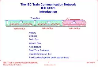
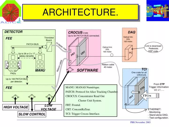
Dimuon Arm. TCI One crate for all CROCUS. From CTP Trigger information: L0, L1…. FTD. TTCrx. FFT. ETHERNET: - Monitoring. Stand alone DAQ. Test configuration. ARCHITECTURE. DETECTOR. DAQ. CROCUS Crate Up to 50 PATCH BUS connected. Optical link: DDL 100 meter. FEE.

E N D
Dimuon Arm TCI One crate for all CROCUS. From CTP Trigger information: L0, L1….. FTD TTCrx FFT • ETHERNET: • - Monitoring. • Stand alone DAQ. • Test configuration. ARCHITECTURE. DETECTOR DAQ CROCUS Crate Up to 50 PATCH BUS connected. Optical link: DDL 100 meter. FEE Translator Board. PATCH BUS 10 Meter max Link to download: Pedestals. DSP code. Optical link: DDL 100 meter. PC CRT Up to 26 or 3 x 17 MANU BOARD. FRT Ribbon cable 40 meter Ribbon cable SOFTWARE MANU 2 x 32 PADs Up to 100 PATCH BUS per detector. MANU: MANAS Numérique. PATCH: Protocol for Alice Tracking Chamber. CROCUS: Concentrator Read Out Cluster Unit System. FRT: Frontal. CRT: ConcentRaTeur. TCI: Trigger Crocus Interface. FEE HIGH VOLTAGE LOW VOLTAGE SLOW CONTROL PRR November 2003
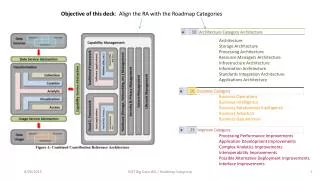
PMD Readout Architecture Total no of cells : 221184 Total no of Modules : 48 1 module = 4608 cells. 1 CROCUS - 50 Patch Buses 6 CROCUS – 300 Patch Buses Patch Bus 2 *32 cells FEEs-Chain Translator DDL LDC CROCUS TCI One crate for all CROCUS. From CTP Trigger information: L0, L1….. 40 meters LVDS LINKPORTS TRIGGER BUSY, and L0 FTD GDC TTCrx FFT • ETHERNET: • - Monitoring. • Stand alone DAQ. • Test configuration.
PMD (Two planes) • CPV • 24 modules • 12 long type • 12 short type • Preshower • 24 modules • 12 long type • 12 short type • 6 CROCUS • 6 DDL (4 PRESHOWER, 2 CPV)
CROCUS#0 • 48 chains • CROCUS#1 • 48 chains P R E S H O W E R CHAIN CONFIGURATION The No. of FEEs has been decided considering the occupancy in that zone
CROCUS#2 • 48 chains • CROCUS#3 • 48 chains P R E S H O W E R CHAIN CONFIGURATION
CROCUS#4 • 45 chains • CROCUS#5 • 45 chains CHAIN CONFIGURATION C P V
Event Logic Structure Event: Base Header (Header extension) Sub-event: Sub-event Base Header Event fragment: Sub-event (Header extension) Equipment Header Event Fragment Sub-event Equipment payload = Common data header + raw data DDL Event Fragment Sub-event LDC GDC
DDL Data Format PATCH bus PATCH bus PATCH bus FRT - DSP 1 PATCH bus PATCH bus Link - port T 1 FRT - DSP 2 Link - port Serial port Parallel bus SIU interface FRT - CRT - DSP 2 FRT - DSP 3 Link - port Link - port T 4 FRT - DSP 4 T 4 T3 T 2 Link - port structDdlHeader FRT - DSP 5 T 3 from FRT - CRT - DSP 2 T 3 from FRT - CRT - DSP 3 T 1 T 2 T 3 stPatchHeader stFrtEvntHeader stFrtCrtEvntHeader struct StDdlHeader { ui32 fui32BlockLengthInBytes; //--------------------------------------------- ui32 fui8FormatVersion :8; ui32 fui8L1TriggerType :8; ui32 fui4Reserved1 :4; ui32 fui12EvntId1BunchCrossing :12; //--------------------------------------------- ui32 fui8Reserved2 :8; ui32 fui24EvntId2OrbitNumber :24; //--------------------------------------------- ui32 fui8BlockAttributes :8; ui32 fui24ParticipSubDetectors :24; //--------------------------------------------- ui32 fui4Reserved3 :4; ui32 fui16StatusErrBits :16; ui32 fui12MiniEvntIdBunchCrossing :12; //--------------------------------------------- ui32 fui32TriggerClassesLow; //--------------------------------------------- ui32 fui4RoiLow :4; ui32 fui10Reserved4 :10; ui32 fui18TriggerClassesHigh :18; //--------------------------------------------- ui32 fui12RoiHigh ; } Raw data T 1 * [ 0 .. 5 ] T 2 * [ 0 .. 5 ] Raw data struct StFrtEventHeader { ui32 fuiFrtDataKey; // 0xF000000F ui32 fuiTotalLength; ui32 fuiRawDataLength; ui32 fuiDspID; ui32 fuiCrt1L1aTriggerCounter; ui32 fuiMiniEvntIdBunchCrossing; ui32 fuiFrtL1aTriggerCounter; ui32 fuiFrtL1rTriggerCounter; bool fbEvenPadded; ui32 fuiErr; } struct StFrtCrtEventHeader { ui32 fuiFrtCrtDataKey; //0xFC0000FC Filled by FrtCrtEventDumper ( Frt-Crt 2&3 ) ui32 fuiTotalLength; // Filled by FrtCrtEventDumper ( Frt-Crt 2&3 ) ui32 fuiRawDataLength; // Filled by FrtCrtEventDumper ( Frt-Crt 2&3 ) ui32 fuiFrtCrtDspID; // Filled by FrtCrtEventDumper ( Frt-Crt 2&3 ) ui32 fuiCrt1L0TriggerCounter; // Filled by DdlDumpingManager (Crt1) ui32 fuiMiniEvntIdBunchCrossing; // Filled by DdlDumpingManager (Crt1) ui32 fuiEvntId1BunchCrossing; // Filled by DdlDumpingManager (Crt1) ui32 fuiEvntId2OrbitNumber; // Filled by DdlDumpingManager (Crt1) // ui32 fuiEvenPadding; // Filled by FrtCrtEventDumper ( Frt-Crt 2&3 ) }; struct StPatchHeader { ui32 fuiPatchDataKey;//0xB000000B ui32 fuiTotalLength; ui32 fuiRawDataLength; ui32 fuiPATCHID; } Note: Note: : DDL TRAILERS 2 Words : 0xD000000D m_uiEvenPadding is just used to make structFrtCrtEvntHeader header size even m_uiEvenPadding=0xDEADBEEF If (bEvenPadded=true T3 block will terminate by junk32 bit word
DATA WORD ( FEE) typedef struct { unsigned adc :12; unsigned channel :6; unsigned fee :11; unsigned unused :2; unsigned parity :1; }PmdRawDataWord; P = Parity bit ( 1 bit) M = FEE board address ( 11 bits ) G = MANAS address ( 2 bits ) C = Channel number ( 4 bits ) D = Data ( 12 bits ) MANAS Adr. 0 0 0 MANAS Adr. 1 0 1 MANAS Adr. 2 1 0 MANAS Adr. 3 1 1 32 31 30 29 28 27 26 25 24 23 22 21 20 19 18 17 15 14 13 12 11 10 9 8 7 6 5 4 3 2 16 1 G G C C C C D D D D D D D D D D D D P 0 0 M M M M M M M M M M M Output Word
Hardware mapping Idea is to convert DDL No., patch Bus No., FEE No., Channel No. to the (x,y) coordinate Done in 2 steps 1. DDL No., PATCH Bus No., FEE address give the physical location Of the FEE Board 2. FEE Board, Channel No give the (x,y) coordinate of the cell
0 8 15 23 31 39 47 Hardware Mapping : Step 1. Module # 0 0 15 31 47 63 79 95 • There are six mapping file for six DDLs. • PMD_Mapping_ddl*.dat contains this mapping. • Once the FEE Board physical loacation within a module is identified, Step-2 is applied
Channel Number to (x,y) : Step 2. This conversion is done Inside the program
Status : Hardware Mapping : done ( Committed to CVS) Raw data reconstruction : in place (CVS), to be tested in this test beam Raw data format : in place (CVS), to be tested in this test beam Removal of gAlice : by 31st October, 2006 Raw2(s)Digits : by 31st October, 2006
CAL T/H CLR CLK-1 MANAS CLK-2 TOKEN-IN CONTROL SIGNALS AD 7476 D ETECTOR Analog Out KM 4110 ADC 0 12 Bit ADC LINK PORT MANAS MARC CS DATA SIGNALS, LPCLK CLK-ADC MANAS TOKEN-OUT AD7476 KM 4110 ADC 1 Analog Out 12 Bit ADC MANAS DIGITAL BUS-LVTTL FEE BOARD CONFIGURATION FEE board Main Components: 1. MANAS (Multiplexed-Analog-Signal- processor ) 2. MARC ( Muon-Arm-Readout-Chip ) 3. ADC (Analog to Digital Converter )
Chain to FEE board connection FEE boards Bridge board Translator board L V FEE board arrangement in short type module Patch bus FEE board arrangement in long type module
DATA WORD 0 0 MANAS Adr. 0 P = Parity bit / M = MANU Address ( 11 Bit ) G = MANAS Address C= Channel number / D = Data ( 12 Bit ) 0 1 MANAS Adr. 1 1 0 MANAS Adr. 2 MANAS Adr. 3 1 1 32 31 30 29 28 27 26 25 24 23 22 21 20 19 18 17 15 14 13 12 11 10 9 8 7 6 5 4 3 2 16 1 G G M M M M M M M M M M M C C C C D D D D D D D D D D D D P 0 0 Output Word