Download
1 / 22
270 likes | 419 Vues
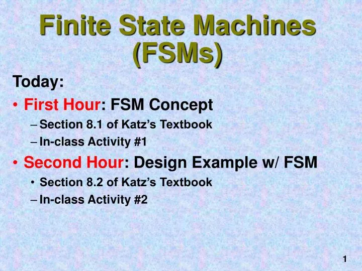
Finite State Machines (FSMs). Today: First Hour : FSM Concept Section 8.1 of Katz’s Textbook In-class Activity #1 Second Hour : Design Example w/ FSM Section 8.2 of Katz’s Textbook In-class Activity #2. Counters vs FSMs. A Precursor of Finite State Machines.

E N D
Finite State Machines (FSMs) • Today: • First Hour: FSM Concept • Section 8.1 of Katz’s Textbook • In-class Activity #1 • Second Hour: Design Example w/ FSM • Section 8.2 of Katz’s Textbook • In-class Activity #2
Counters vs FSMs A Precursor of Finite State Machines • Counters: Simple sequential circuits State = Output No inputs Simple single-path sequencing through the states • Generalizes to Finite State Machines: Outputs are Function of State (and Inputs) Next States are Functions of State and Inputs Used to implement circuits that control other circuits "Decision Making" or “control” logic
Described by State Diagrams, much the same way that combinational logic circuits are described by Boolean Algebra. Recap: Synchronous FSMs Current State [output] New State [output] Current Input(s) Change of state happens only on the clocking event
Recap:3-bit Binary Up-Counter 001 001 010 010 000 000 Each circle corresponds to a state The label inside each circle describes the state 011 011 111 111 Arrows represent state transitions 101 101 100 100 110 110 No labels on arrows, since the counter has no inputs
Reset 0 Even [0] 1 Symbolic State Transition Table 1 Odd [1] 0 State Diagram Encoded State Transition Table Example: Odd Parity Checker Asserts output whenever input bit stream (seen so far) has odd # of 1's Observe that the output in this case depends only upon the present state, and not upon the input.
Q Q+ T 0 0 0 0 1 1 1 0 1 1 1 0 Design with Flip-flops Q Q+ D 0 0 0 0 1 1 1 0 0 1 1 1 T F/F: Excitation Table D F/F: Excitation Table D F/F inputs are identical to the next state outputs in the state transition table
Excitation/Output Functions D = PS Input; Output = PS Output Input Q D T Input Clock D Q PS/Output Q Clock R Q R \Reset \Reset D FF Implementation T FF Implementation Input 1 0 0 1 1 0 1 0 1 1 1 0 Clock 1 1 1 0 1 1 0 0 1 0 1 1 Output Timing Behavior: Input 1 0 0 1 1 0 1 0 1 1 1 0 Odd Parity Checker Operation
Timing When are inputs sampled, next states computed, outputs asserted? State Time: Time between clocking events • Clocking event causes state/outputs to transition, based on inputs • For set-up/hold time considerations: Inputs should be stable before clocking event • After propagation delay, Next State entered, Outputs are stable NOTE: Asynchronous signals take effect immediately Synchronous signals take effect at the next clocking event E.g., 3-state enable: effective immediately sync. counter clear: effective at next clock event
State Time Clock Inputs Outputs Timing Example Positive Edge Triggered Synchronous System On rising edge: inputs sampled, outputs & next state computed After propagation delay: outputs and next state are stable Immediate Outputs affect datapath immediately could cause inputs from datapath to change Delayed Outputs take effect on next clock edge propagation delays must exceed hold times
Communicating State Machines One machine's output is another machine's input [0], [1] outputs • Could be used to model: • bus protocols, handshaking, • 2-way communications, etc. Machines advance in lock step Initial inputs/outputs: X = 0, Y = 0
Basic Design Approach Six Step Process • 1. Understand the statement of the Specification • 2. Obtain an abstract specification of the FSM • 3. Perform a state minimization • 4. Perform state assignment • 5. Choose FF types to implement FSM state register • 6. Implement the FSM
Vending Machine Concept General Machine Concept • deliver package of gum after 15 cents is deposited • single coin slot for dimes, nickels • no change
INPUTSOUTPUTS Block Diagram Vending Machine FSM - 1 Step 1. Understand the problem Draw a picture!
Tabulate typical input sequences three nickels nickel, dime dime, nickel two dimes two nickels, dime Draw state diagram Inputs: N, D, reset Output: open Vending Machine FSM - 2 Step 2. Map into more suitable abstract representation
reuse states whenever possible Symbolic State Table Vending Machine FSM - 3 Step 3: State Minimization
Vending Machine FSM - 4 Step 4: State Encoding How many flip-flops are needed?
Q1 Q1 Q1 Q1 Q0 Q1 Q0 Q1 Q0 D N D N D N N N N D D D Q0 Q0 Q0 K-map for D1 K-map for D0 K-map for Open Vending Machine FSM - 5a Step 5. Choose F/Fs for implementation D F/F easiest to use
J-K F/F Present State Inputs Next State J J K K 1 1 0 0 Q Q Q1+ Q0+ D N 1 0 0 0 0 0 0 X 0 X 0 0 0 1 0 X 1 X 0 1 1 0 1 X 0 X 1 0 X X X X X X 1 1 0 1 0 1 0 X X 0 0 0 1 0 1 X X 1 0 1 1 1 1 X X 0 1 0 X X X X X X 1 1 1 0 1 0 X 0 0 X 0 0 1 1 X 0 1 X 0 1 1 1 X 0 1 X 1 0 X X X X X X 1 1 1 1 1 1 X 0 X 0 0 0 1 1 X 0 X 0 0 1 X 1 1 X 0 0 1 0 X X X X X X 1 1 Remapped encoded state transition table Vending Machine FSM - 5b Step 5. Choose FF for Implementation (continued)
D1 = Q1 + D + Q0 N D0 = N Q0 + Q0 N + Q1 N + Q1 D OPEN = Q1 Q0 Vending Machine FSM - 6a Step 6. Implementation: D F/Fs 8 Gates
Q1 Q1 J1 = D + Q0 N K1 = 0 J0 = Q0 N + Q1 D K0 = Q1 N Q1 Q0 Q1 Q0 D N D N N N D D Q0 Q0 K-map for J1 K-map for K1 Q1 Q1 Q1 Q0 Q1 Q0 D N D N N N D D Q0 Q0 K-map for J0 K-map for K0 Vending Machine FSM - 6b Step 6. Implementation: J-K F/Fs 7 Gates
Do Activity #2 Now • Due: End of Class Today. • RETAIN THE LAST PAGE(S) (#3 onwards)!! • For Next Class: • Bring Randy Katz Textbook, & TTL Data Book • Required Reading: • Sec 8.4 of Katz • This reading is necessary for getting points in the Studio Activity!