Download

1 / 69
750 likes | 1.04k Vues
Image Formation and Representation. CS485/685 Computer Vision Dr. George Bebis. A Simple model of image formation. The scene is illuminated by a single source. The scene reflects radiation towards the camera. The camera senses it via solid state cells (CCD cameras). Image formation (cont’d).

E N D
Image Formation and Representation CS485/685 Computer Vision Dr. George Bebis
A Simple model of image formation • The scene is illuminated by a single source. • The scene reflects radiation towards the camera. • The camera senses it via solid state cells (CCD cameras)
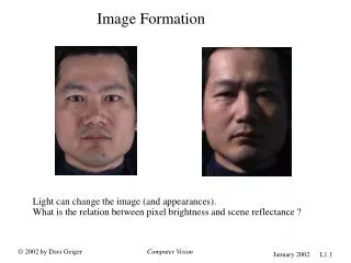
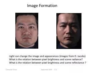
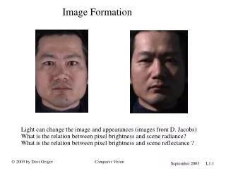
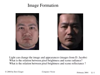
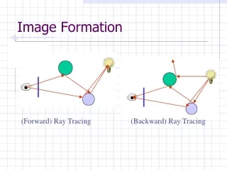
Image formation (cont’d) • There are two parts to the image formation process: • The geometry, which determines where in the image plane the projection of a point in the scene will be located. (2) The physics of light, which determines the brightness of a point in the image plane. f(x,y) = i(x,y) r(x,y) Simple model: i: illumination, r: reflectance
Let’s design a camera Put a piece of film in front of an object - do we get a reasonable image? Blurring - need to be more selective!
Let’s design a camera (cont’d) Add a barrier with a small opening (i.e. aperture) to block off most of the rays Reduces blurring
center of projection (x,y) “Pinhole” camera model • The simplest device to form an image of a 3D scene on a 2D surface. • Rays of light pass through a "pinhole" and form an inverted image of the object on the image plane. perspective projection: (X,Y,Z) f: focal length
What is the effect of aperture size? Large aperture: light from the source spreads across the image (i.e., not properly focused), making it blurry! Small aperture: reduces blurring but (i) it limits the amount of light entering the camera and (ii) causes light diffraction.
Example: varying aperture size (cont’d) • What happens if we keep decreasing aperture size? • When light passes through a small hole, it does not travel in a straight line and is scattered in many directions (i.e., diffraction) SOLUTION: refraction
Refraction • Bending of wave when it enters a medium where its speed is different.
Lens • Lens duplicate pinhole geometry without resorting to undesirably small apertures. • Gather all the light radiating from an object point towards the lens’s finite aperture . • Bring light into focus at a single distinct image point. refraction
Lens (cont’d) • Lens improve image quality, leading to sharper images.
Properties of “thin” lens (i.e., ideal lens) Light rays passing through the center are not deviated. Light rays passing through a point far away from the center are deviated more. focal point f
Properties of “thin” lens (i.e., ideal lens) All parallel rays converge to a single point. When rays are perpendicular to the lens, it is called focal point. focal point f
Properties of “thin” lens The plane parallel to the lens at the focal point is called the focal plane. The distance between the lens and the focal plane is called the focal length (i.e., f) of the lens. focal point f
Thin lens equation object v u f image Assume an object at distance u from the lens plane:
Thin lens equation (cont’d) v u f y y’ Using similartriangles: y’/y = v/u image
Thin lens equation (cont’d) Using similartriangles: v u f y y’ y’/y = (v-f)/f image
Thin lens equation (cont’d) + = u v f 1 1 1 Combining the equations: v u f image
Thin lens equation (cont’d) The thin lens equation implies that only points at distance u from the lens are “in focus” (i.e., focal point lies on image plane). Other points project to a “blur circle” or “circle of confusion” in the image (i.e., blurring occurs). + = u v f 1 1 1 “circle of confusion”
Thin lens equation (cont’d) When objects move far away from the camera, then the focal plane approaches the image plane. + = u v f focal point f 1 1 1
Depth of Field The range of depths over which the world is approximately sharp (i.e., in focus). http://www.cambridgeincolour.com/tutorials/depth-of-field.htm
How can we control depth of field? • The size of blur circle is proportional to aperture size.
How can we control depth of field? (cont’d) Changing aperture size (controlled by diaphragm) affects depth of field. A smaller aperture increases the range in which an object is approximately in focus (but need to increase exposure time). A larger aperture decreases the depth of field (but need to decrease exposure time).
Varying aperture size Large aperture = small DOF Small aperture = large DOF
Another Example Large aperture = small DOF
Field of View (Zoom) f f • The cone of viewing directions of the camera. • Inversely proportional to focal length.
Reduce Perspective Distortions by varying Distance / Focal Length Small f (i.e., large FOV), camera close to car Large f (i.e., small FOV), camera far from car Less perspective distortion!
Same effect for faces standard wide-angle telephoto Less perspective distortion! Practical significance: we can approximate perspective projection using a simpler model when using telephoto lens to view a distant object that has a relatively small range of depth.
Approximating an “affine” camera Center of projection is at infinity!
Real lenses • All but the simplest cameras contain lenses which are actually • comprised of several "lens elements." • Each element aims to direct the path of light rays such that they • recreate the image as accurately as possible on the digital sensor.
Lens Flaws: Chromatic Aberration Lens has different refractive indices for different wavelengths. Could cause color fringing: i.e., lens cannot focus all the colors at the same point.
Lens Flaws: Radial Distortion Straight lines become distorted as we move further away from the center of the image. Deviations are most noticeable for rays that pass through the edge of the lens.
Lens Flaws: Radial Distortion (cont’d) No distortion Pin cushion Barrel
Lens Flaws: Tangential Distortion • Lens is not exactly parallel to the imaging plane!
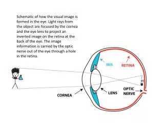
Human Eye • Functions much like a camera: • aperture (i.e., pupil), lens, mechanism for focusing (zoom in/out) • and surface for registering images (i.e., retina)
Human Eye (cont’d) • In a camera, focusing at various distances is achieved by varying the distance between the lens and the imaging plane. • In the human eye, the distance between the lens and the retina is fixed (i.e., 14mm to 17mm).
Human Eye (cont’d) • Focusing is achieved by varying the shape of the lens (i.e., flattening of thickening).
Human Eye (cont’d) • Retina contains light sensitive cells that convert light energy into electrical impulses that travel through nerves to the brain. • Brain interprets the electrical signals to form images.
Human Eye (cont’d) • Two kinds of light-sensitive cells: rods and cone (unevenly distributed). • Cones (6 – 7 million) are responsible for all color vision and are present throughout the retina, but are concentrated toward the center of the field of vision at the back of the retina. • Fovea – special area • Mostly cones. • Detail, color sensitivity, and resolution are highest.
Human Eye (cont’d) • Three different types of cones; each type has a special pigment that is sensitive to wavelengths of light in a certain range: • Short (S) corresponds to blue • Medium (M) corresponds to green • Long (L) corresponds to red • Ratio of L to M to S cones: • approx. 10:5:1 • Almost no S cones in the center of the fovea
Human Eye (cont’d) • Rods (120 million) more sensitive to light than cones but cannot discern color. • Primary receptors for night vision and detecting motion. • Large amount of light overwhelms them, and they take a long time to “reset” and adapt to the dark again. • Once fully adapted to darkness, the rods are 10,000 times more sensitive to light than the cones
Digital cameras A digital camera replaces film with a sensor array. Each cell in the array is light-sensitive diode that converts photons to electrons Two common types Charge Coupled Device (CCD) Complementary metal oxide semiconductor (CMOS) • http://electronics.howstuffworks.com/digital-camera.htm
CCD Cameras CCDs move photogenerated charge from pixel to pixel and convert it to voltage at an output node. An analog-to-digital converter (ADC) then turns each pixel's value into a digital value. http://www.dalsa.com/shared/content/pdfs/CCD_vs_CMOS_Litwiller_2005.pdf
CMOS Cameras CMOs convert charge to voltage inside each element. Uses several transistors at each pixel to amplify and move the charge using more traditional wires. The CMOS signal is digital, so it needs no ADC. http://www.dalsa.com/shared/content/pdfs/CCD_vs_CMOS_Litwiller_2005.pdf
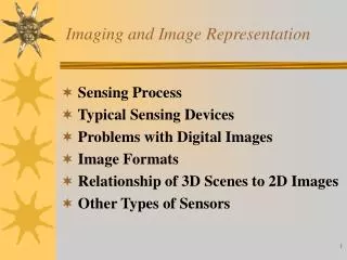
Image digitization • Sampling: measure the value of an image at a finite number of points. • Quantization: represent measured value (i.e., voltage) at the sampled point by an integer.
Image digitization (cont’d) Quantization Sampling