Download
1 / 40
490 likes | 933 Vues
Airborne Laser Scanning: Remote Sensing with LiDAR. ALS / LIDAR OUTLINE. Laser remote sensing background Basic components of an ALS/LIDAR system Two distinct families of ALS systems Waveform Discrete Return (small footprint) Working with the data, processing requirements

E N D
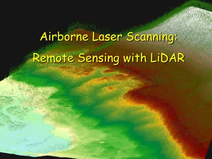
Airborne Laser Scanning: Remote Sensing with LiDAR
ALS / LIDAR OUTLINE • Laser remote sensing background • Basic components of an ALS/LIDAR system • Two distinct families of ALS systems • Waveform • Discrete Return (small footprint) • Working with the data, processing requirements • Current applications and developing applications • Advancing ALS / LiDAR technology
Airborne Laser Scanning • ALS/LiDAR is an active remote sensing technology that measures distance with reflected laser light. LiDAR: LIghtDetection and Ranging or Laser Imaging Detection and Ranging) • 1st developed in 1960 by Hughes Aircraft inc. • Modern computers and DGPS make it practical. • Typically used in very accurate mapping of topography. • New technologies and applications are currently being developed.
Why use a Laser? ALS systems take advantage of two of the unique properties of laser light: 1. The laser is monochromatic. It is one specific wavelength of light. The wavelength of light is determined by the lasing material used. Advantage: We know how specific wavelengths interact with the atmosphere and with materials. 2. The light is very directional. A laser has a very narrow beam which remains concentrated over long distances. A flashlight (or Radar) on the other hand, releases energy in many directions, and the energy is weakened by diffusion. Advantage: The beam maintains its strength over long distances. 3mrad divergence = 30 cm at 1 km and 1.5m at 5 km.
Radians • A full angle is 2π radians, so there are 360° per 2π radians, equal to 180°/π or 57.29° / radian. • A milliradian (mrad) is 1/1000 radian. • 3 mrad = 3*0.05729°.
ALS mapping concepts • The position of the aircraft is known (from DGPS and IMU-Inertial Measurrment Unit). • Measures distance to surfaces by timing the outgoing laser pulse and the corresponding return (s). • Distance = time*(speed of light)/2 • By keeping track of the angle at which the laser was fired: you can calculate the X, Y, Z position of each “return”. • Requires extremely accurate timing and a very fast computer.
Basic ALS System Components • Laser (usually NIR –1064nm) mounted in an aircraft. • Scanning assembly – precisely controlled rotating mirror. • Receiver for recording reflected energy “Returns”. • Aircraft location system incorporating Differential GPS and Inertial Navigation System(INS, = IMU). • A very fast computer to synchronize and control the whole operation.
Two Distinct Families of ALS Systems Waveform systems (a.k.a. large-footprint) Records the COMPLETE range of the energy pulse (intensity) reflected by surfaces in the vertical dimension. Samples transects in the horizontal (X,Y) plane. Waveform systems designed to capture vegetation information are not widely available. Waveform systems include SHOALS, SLICER, LVIS, ICESat. Discrete-return systems (a.k.a. small-footprint or topographic) SAMPLES the returned energy from each outgoing laser pulse in the vertical plane (Z) (if the return reflection is strong enough). Most commercial lidar systems are discrete return, many different types are available.
Waveform LIDAR This is the “waveform” graph of energy intensity Notice that it follows the “shape” of the tree biomass
Waveform LIDAR: SLICER Waveform systems have been used to accurately measure (r2 >.90) vertical distribution of tropical and temperate forests (Lefsky 2001)
Spaceborne LIDAR: ICEsat and VCL Spaceborne waveform LIDAR systems. ICEsat launched in 2003 for survey of topography and polar ice. VCL (Vegetation Canopy LIDAR) was designed to sample 5 separate widely spaced tracks with 25m footprint waveforms. Has been cancelled. Do not provide “wall to wall” mapping.
Discrete-return LIDAR • Records data as X,Y,Z points. • Spatial resolution is expressed in terms of “post spacing” which is the avg. horizontal distance between points. • Returns are “triggered” if the laser reflects from a surface large enough to exceed a pre-set energy threshold. • Minimum vertical distance between returns is ~ 5 meters. • New capability to record the intensity of point returns.
Discrete Return Data: Millions of X,Y,Z points Area is approximately: 1 X 0.75mi. includes ~ 440,000 returns
From Point Clouds to 3-D Surface Models • Points are used to create 3D surface models for applications. • Triangular Irregular Networks (TIN)s are used to classify the points and to develop Digital Elevation Models (DEM)s. • Points must be classified before use: “bare earth” points hit the “ground”; other point categories include tree canopy and buildings. • Correct identification of “bare earth” is critical for any lidar mapping application.
Working with Commercial LIDAR Discrete return lidar data requires several complex processing steps to develop useable products. These steps are usually divided into two phases: Pre-processing is the preparation of the raw data, correcting for errors induced by flight geometry, removing overlaps between flight lines, surfacing, and accuracy assessment of the raw point locations. Post-processing is the development of usable information from the point clouds including development of TINs, DEMs, and other products like canopy height maps. Pre-processing is always done by the lidar contractor.
Discrete Return LIDAR Accuracy • Average reported point location accuracies for a hard flat reflective surface (e.g. airport runway): 2-15 cm vertical 25-100 cm horizontal • Reported measurement accuracies: (forestry research, best cases) Height prediction r2 = 0.93 (Means 2000) Volume prediction r2 = 0.92 (Maclean and Krabill 1992) Comparing field measurements to laser measurements • Timing system accuracy is critical: 1 nanosecond = 30cm • Accuracy is also affected by errors in GPS, surfacing and data analysis. • Measurements of object height requires accurate surfacing to provide accurate base height.
Applications for Discrete-Return LIDAR Digital Elevation Model (DEM) 4m DEM of PREF Subset
Geomorphology Mapping geomorphic features (Puget Sound LiDAR Consortium)
Geology Mapping Faults (Puget Sound LiDAR Consortium)
Other Applications Measuring volume change in open pit mines. Utilities use lidar to map power transmission line curvature and clearance.
Discrete Return LIDAR for Forestry • Can be used to measure forest characteristics including stand height, biomass distribution, volume. • DEMs are used in planning for erosion and engineering projects including roads. • Mapping of forest stand structure characteristics and fire fuels conditions is under development.
The Future of ALS ALS/LIDAR technology is evolving rapidly, the next 10 years will bring many new capabilities and applications. • Systems now available record 50,000 pps. Expect to see 100,000 pps systems soon. • Automatic merging of multi-spectral imagery with LIDAR is being developed now. • Laser induced fluorescence and measurement of changes in laser coherence and polarization will provide more information about the surfaces that the laser light interacts with. • Look for multi-spectral LiDAR using multiple lasers in different frequencies recording intensity to spectrally identify surface materials.
New ALS Technologies This is an example of a new application that merges lidar and multi-spectral imagery to automatically classify features. • Expect higher data density: current systems operate at 15,000hz; • New systems operate at 50,000hz, • Next generation will be 100,000hz +
Concepts to Remember About ALS • ALS/LIDAR is an active remote sensing technology designed to take advantage of the unique properties of laser light. • Two basic families of lidar systems exist: waveform and discrete-return. • Commercially available lidar is discrete-return, it is used in for a number of applications. • Accuracy of ALS depends on a number of highly complex interacting factors. • Complex processing steps are required to use lidar and accurate surfacing is critical for applications measuring object heights. • Development of lidar technology is occurring at a rapid pace, new applications will be developed.