Download
1 / 23
230 likes | 398 Vues
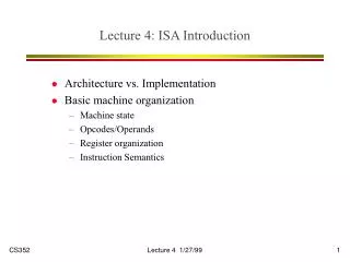
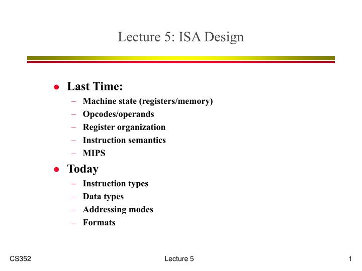
Lecture 5: ISA Design. Last Time: Machine state (registers/memory) Opcodes/operands Register organization Instruction semantics MIPS Today Instruction types Data types Addressing modes Formats. Mem. Mem. Regs. Regs. Before State. After State. ISA Basics. instruction.

E N D
Lecture 5: ISA Design Last Time: Machine state (registers/memory) Opcodes/operands Register organization Instruction semantics MIPS Today Instruction types Data types Addressing modes Formats
Mem Mem Regs Regs Before State After State ISA Basics instruction Instruction formats Instruction types Addressing modes Op Mode Ra Rb Data types Operations Interrupts/Events Machine state Memory organization Register organization
In the beginning…the accumulator 2 instruction types: op and store A A op M A A op *M *M A a one address architecture each instruction encodes one memory address 2 addressing modes immediate: M direct addressing: *M Early machines: EDVAC, EDSAC... Evolution of Register Organization FFF Memory PC Accumulator 0 Machine State Address (M) Op Instruction Format (Op encodes addressing mode)
Why Accumulator Architectures? • Registers expensive in early technologies (vacuum tubes) • Simple instruction decode • Logic also expensive • Critical programs were small (efficient encoding) • Less logic faster cycle time • Model similar to earlier “tabulating” machines • Think adding machine
Add an indexed addressing modeA A op (M+I) *(M+I) A good for array access: x[j] address of x[0] in instruction j in index register one register for each key function PC instructions I data addresses A data values new instructions to use I INC I, CMP I, etc. The Index Register FFF Index Memory PC Accumulator 0 Machine State Address (M) Op Instruction Format
Example of Indexed Addressing sum = 0; for(i=0; i<n; i++) sum = sum + y[i]; START: CLR i CLR sumLOOP: LOAD IX AND #MASK OR i STORE IX LOAD sumIX: ADD y STORE sum LOAD i ADD #1 STORE i CMP n BNE LOOP START: CLRA CLRXLOOP: ADDA y(X) INCX CMPX n BNE LOOP With Index Register Without Index Register
But What About... sum = 0; for(i=0; i<n; i++) for(j=0; j<n; j++) sum = sum + x[j]*y[i];
Merge accumulators (data) and index (address) Any register can hold variable or pointer simpler more orthogonal (opcode independent of register usage) More fast local storage but….addresses and data must be same size How many registers? More - fewer loads and stores But - more instruction bits General Registers FFF PC Rn-1 Memory R1 R0 0 Machine State i j k Op 3-address Instruction Format
Register state is PC and SP All instructions performed on TOS (top of stack) and SOS pushes/pops of stack implied op TOS SOS op TOS M op TOS *M op TOS *(M+SP) Many instructions are zero address Stack cache for performance similar to register file hardware managed Why do we care? JVM Memory PC Cur Inst SP Code TOS TOS SOS Stack Stack $ Stack Machines
Examples of Stack Code a = b + c * d; e = a + f[j] + c; PUSH d PUSH c MUL PUSH b ADD PUSH j PUSHX f PUSH c ADD ADD POP e LOAD R1, d LOAD R2, c MUL R3, R1, R2 LOAD R4, b ADD R5, R4, R3 LOAD R6, j LOAD R7, f(R6) ADD R8, R7, R2 ADD R9, R5, R8 STORE e, R9 PUSH d MUL c ADD b PUSH j PUSHX f ADD c ADD POP e Pure Stack One Address Stack Load/Store (zero addresses) (many GP registers) 8 inst, 7 addr 10 inst, 6addr 11 inst, 7 addr
Op Address, M Review of Register Organization Accum. Accum+Index GPR Stack PC PC PC PC Accumulator Accumulator Rn-1 SP Index R1 R0 Op i j k M
Keep it simple (KISS) complexity increases logic area increases pipe stages increases development time evolution tends to make kludges Orthogonality (modularity) simple rules, few exceptions all ops on all registers Frequency make the common case fast some instructions (cases) are more important than others Principles of Instruction Set Design Data Types Regs Operations Formats Add Modes
Generality not all problems need the same features/instructions principle of least surprise performance should be easy to predict Locality and concurrency design ISA to permit efficient implementation today 10 years from now F F F F D D D D R R R R E E E E W W W W Principles of Instruction Set Design (part 2) vs
ALU Operations arithmetic (add, sub, mult, div) logical (and, or, xor, srl, sra) data type conversions (cvtf2d, cvtf2i) Data Movement memory reference (lb, lw, sb, sw) register to register (movi2fp, movf) Control - what instruction to do next tests/compare (slt, seq) branches and jumps (beq, bne, j, jr) support for procedure call (jal, jalr) operating system entry (trap) Hair - string compare! Instruction Types
Memory Organization • Four components specified by ISA: • Smallest addressable unit of memory (byte? halfword? word?) • Maximum addressable units of memory (doubleword?) • Alignment • Endianness
unaligned word access 0x1004 0x1000 Alignment • Some architectures restrict addresses that can be used for particular size data transfers! • Bytes accessed at any address • Halfwords only at even addresses • Words accessed only at multiples of 4
0 3 2 1 0 3 0x1004 0x1003 0x1002 0x1001 0x1000 0x0fff 3 0 1 2 3 0 0x1004 0x1003 0x1002 0x1001 0x1000 0x0fff Endianness • How are bytes ordered within a word? • Little Endian (Intel/DEC) • Big Endian (MIPS/IBM/Motorola) • Today - most machines can do either (configuration register)
How the contents of memory and registers are interpreted Can be identified by tag use Driven by application Signal processing 16-bit fixed point (fraction) Text processing 8-bit characters Scientific computing 64-bit floating point Most general purpose computers support several types 8, 16, 32, 64-bit signed and unsigned fixed and floating int 0x8a1c str “abcd” Data Types
Example: 32-bit Floating Point 23 • Type specifies mapping from bits to real numbers (plus symbols) • format • S, 8-bit exp, 23-bit mantissa • interpretation • mapping from bits to abstract set • operations • add, mult, sub, sqrt, div 1 8 s exp mantissa
Addressing ModesDriven by Program Usage double x[100] ;// globalvoid foo(int a) {// argumentint j ;// local for(j=0;j<10;j++) x[j] = 3 + a*x[j-1] ; bar(a);} Memory Stack j a x procedure array reference bar constant argument foo
Addressing Modes Memory SP • Stack relative for locals and arguments a, j: *(R30+x) • Short immediates (small constants) 3 • Long immediates (global addressing) &x[0], &bar: 0x3ac1e400 • Indexed for array references *(R4+R3) Stack j a x bar foo
#n immediate (0x1000) absolute Rn Register (Rn) Register indirect -(Rn) predecrement (Rn)+ postincrement @(Rn) Memory indirect @(Rn)+ postincrement d(Rn) Displacement (b,w,l) d(Rn)[Rx] Scaled Addressing Mode Summary VAX 11 had 27 addressing modes (why?)
Next Time • RISC vs CISC • ISA Comparisons • The role of the compiler