Download
1 / 22
220 likes | 349 Vues
Electronics Status. Trigger and DAQ run successfully in RUN2006 for the first time Trigger communication to DRS boards via trigger bus Trigger firmware and DRS firmware was modified during beam time and downloaded

E N D
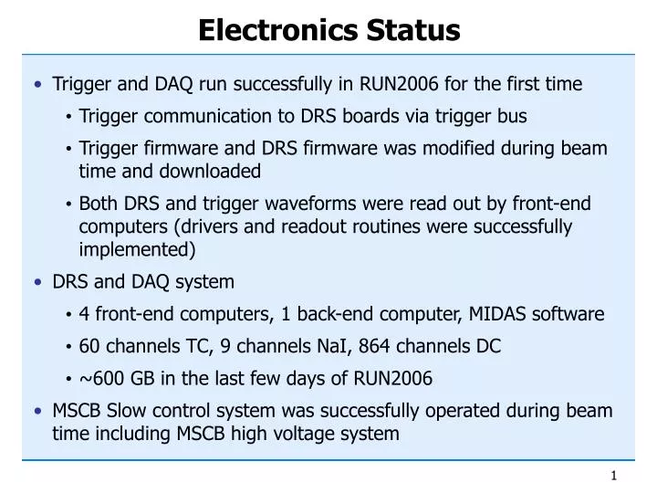
Electronics Status • Trigger and DAQ run successfully in RUN2006 for the first time • Trigger communication to DRS boards via trigger bus • Trigger firmware and DRS firmware was modified during beam time and downloaded • Both DRS and trigger waveforms were read out by front-end computers (drivers and readout routines were successfully implemented) • DRS and DAQ system • 4 front-end computers, 1 back-end computer, MIDAS software • 60 channels TC, 9 channels NaI, 864 channels DC • ~600 GB in the last few days of RUN2006 • MSCB Slow control system was successfully operated during beam time including MSCB high voltage system
2 boards LXe front face (216 PMTs) 2 x 48 5+5+2 boards LXe lateral faces back (216 PMTs) 4 in 1 lat. (144x2 PMTs) 4 in 1 up/down (54x2 PMTs) 4 in 1 . . . 14 boards . . . 1 board Type2 Type2 Type2 Type2 Type2 14x 48 9 x 48 2 x 48 Type1 Type1 Type1 Type1 Type1 Type1 Type1 Type1 Type1 Type1 Type1 Type1 1 board Timing counters curved (640 APDs) 8 in 1 u/d stream(30x2 PMTs) 4 4 4 4 4 16 16 16 16 16 16 1 x 48 9 boards 1 board . . . 2 boards 9x 48 Drift chambers 16 +16 channels 2x 48 Auxiliary devices 16 (9) channels 1 x 48 Trigger System Structure
ARGUS monitor (scalers) Rate of individual channels (independent of trigger)
Trigger scheme for TC AL (mV) AR (mV) excluded excluded AL > 50 mV && AR > 50 mV && AL+AR > 200 mV excluded trigger selection independent of z 50 mV threshold ~ 100150 mV at PMT output
Trigger Waveforms Trigger window …
Efficiency study low intensity (slit = 10%) high intensity (slit = 100%) ms ms events associated with the trigger signal “unbiased” events (out of trigger window and with 10 mV threshold)
Efficiency profile (all PMTs) Secondary particles Unbiased (10mV) Trigger (50mV & 200mV) rescaled by RpulseT Landau peak for e+ = NT/NU Interpolation by erf function Npe almost full efficiency at Landau peak(~6MeV, ~500pe)
Trigger Conclusions • Trigger system was completed and installed last • summer (both Hardware and Firmware) • Successfully linked to DRS & DAQ online • Monitor tools developed • Properly worked during December run • TC event selection • WFD for PMTs • Proved to be~100% efficient for energy losses in the Landau peak • Very low noise (RMS~0.4 mV)
Trigger pE5 area Trigger ‘cave’ Trigger Trigger Ancillary system clock start stop sync Front-End PCs PC (Linux) PC (Linux) PC (Linux) PC (Linux) Run start Run stop Trigger config PC (Linux) 3 crates DRS PC (Linux) DRS Busy PC (Linux) DRS DRS PC (Linux) DRS PC (Linux) Event builder DRS 20 MHz clock PC (Linux) Hit registers PC (Linux) PC (Linux) Trigger signal Event number Trigger type 6 crates Gigabit Ethernet PC (Linux) PC (Linux) On-line farm storage DAQ Cluster
Offline Cluster • 5 x 4 CPUs SunFire X4100 • 30 TB disk storage • Planned in ’07: 64 CPU + 100 TB disk lcmeg05 lcmeg04 lcmeg03 lcmeg02 lcmeg01
Correlation DRS vs. Trigger waveform • Signal height of DRS waveform (10:1) – Trigger waveform (2.5:1)
Crosstalk removal Reduction of (coherent) noise band cross talk by averaging “empty” channels and subtracting signal channels: Noise level: 0.5 mV → 0.32 mV Baseline fluctuation (100 ns): 0.27 mV → 0.07 mV
200 ns Integral if no pile-up 500 ns Overall Data Rate • Now had 2.8 MB events (50% DC + TC, no LXe) and could run at ~10 Hz • Full detector estimates: 9 MB/event, 5 Hz, 650 TB/year • Zero suppression (50% on LXe, 80% on DC) • ADC/TDC values for non-signal-like events • Partial waveform readout (reduced window size) • 3rd level trigger in online cluster • Applying all this techniques: • 100 Hz “ADC rate” • 6 Hz “Waveform rate” 100Hz 30 TB/year DRS firmware
DRS3 status • All channels are currently equipped with DRS2, ran reasonably well during beam time • DRS2 shows temperature dependence which should be fixed with DRS3 chip (improved amplitude accuracy) • 50 Prototypes DRS3 have been delivered • Test board PCB is in production • Test chip until March ’07 • Mass production in summer ’07 if tests ok • Replace DRS2 by DRS3in 2007/08 shutdown
MSCB slow control overview Cluster Switch • 8 Ethernet “Submasters” • 4+ SCS-2000 units each with up to 64 I/O • HV system with 1054 channels
HV system • 900 channels for LXe calorimeter • Designed and built at PSI • 24-bit ADCs for high accuracy (20mV) • Once micro controller per five channels • Read out every 4 seconds • 60 channels TC + 64 channels APD • Run stably in last beam time • Redesign of MSCB protocol resultedin increased readout speed (4 sec. forall channels, 0.5 sec. for last modified)
Future Plan • Fine-tune trigger firmware as detectors come online • Increase DAQ speed to 100 Hz until next beam time • Data reduction (Tokyo Workshop end of March ’07) • 3rd level trigger • Improve front-end code and DRS firmware • Replace DRS2 by DRS3 • If tests of DRS3 are successful, replace towards end ’07 • If DRS3 is not working, redesign required (+0.5 y) • Finances • All electronics bought • Spare PSI funds for DRS3 allocated • Funding of extension of offline cluster secured (PSI part)