Download

1 / 37
370 likes | 485 Vues
Part B Orthopedic BloOpers. Scatter. 28. Scatter.

E N D
Part B • Orthopedic BloOpers
Scatter 28
Scatter • At UCLA, the vast majority of projectional imaging is performed using Computed Radiography (CR) or Direct Capture Radiography (DR). Both of these digital imaging technologies are more sensitive to scatter radiation than traditional film/screen imaging. • Always ask yourself the following when finalizing your technique • 1. Do I have adequate collimation for the body part? • 2. Is this the lowest possible kVp while still penetrating the body part of interest? • 3. Is the body part thick enough for a grid? If you are not sure, go with the grid? 29
This portable T-Spine was turned in without any explanation in RIS as to why the quality is so poor. The lateral spine shows significant image degradation due to scatter. The next slide is the report for this exam. 30
Image quality problems: 1. Multiple views on one plate. 2. Excessive scatter on lateral knee, double exposing the oblique knee. 3. Knee is bent at 90 degrees, limiting evaluation for effusion. Flexion should be no more than 20-30 degrees. 32
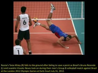
Exam ordered: portable femur. Reason for exam: femur and acetabular facture. While this study was performed portably, a grid is required for any body part that has the potential for creating large amounts of scatter. Image quality has been completely compromised by excessive scatter radiation and the Radiologist reports the hip joint cannot be seen on either view. 33
Scatter greatly reduces the visualization of any bone detail in this large shoulder study. In the absence of a grid the scatter radiation is left unchecked and completely destroys any detail with visualization reduced to the shadow of bones. The study is undiagnostic and must be repeated with a grid. 34
What artifact do you see here? Did you get it right? “Motion” sometimes falls within the artifact category. Motion is considered one of the biggest contributors to image unsharpness. Can you name another contributor to image unsharpness? Contrast and visual sharpness are directly related. A long scale of gray, as with images displaying a lot of scatter will typically lack sharpness. 35
Artifacts 36
The wavy line artifact here is called a moire pattern. This artifact is produced when the digital acquisition device and the grid ratio are not compatible. Each digital projectional manufacturer (Fuji, GE etc.) has recommended grid ratios that are specific for their system. To avoid morie patterns be sure to use only the specific grid ratio suggested by each manufacture. 37
Digital technology has far reaching grayscale capability. Excessive sheet, blanket and gown folds will show up on most studies. Two right markers are not necessary. Snaps What artifacts do you see here? 38 38
39 When performing quality assurance on each image, the technologist should look closely at all aspects of the image. This includes any subtle artifacts that may make the diagnosis difficult. If you take time to stop and really evaluate your image, these artifacts are easily picked up.
Imaging plates can easily pick up dirt and degrade image quality, be sure to establish a schedule for plate cleaning, at least one time per month to avoid excessive plate artifacts. 40
This artifact showed up on four different patients before it was uncovered. The images here are two separate patients. 41
This piece of metal was finally found embedded in the table pad. 42
Could this be removed? If yes, repeat the exam. 43
Good example of one little line, sitting exactly over the anatomy of interest. 44
Lines and tubes, especially when bundled together create large artifacts, in this case completely obscuring the body of C-5. 48
Markers 49
Markers • Lead markers must be used to identify left/right body side • when performing a digital projectional exam. • Some exceptions are the OR and sterile conditions. 50
In this thumb series the technologist placed a lead marker but placement fell outside the collimated edge. In this case, use the electronic markers at the QC workstation to correct the mistake. 51
This marker was not placed on the finger tuff, the patient moved and the marker fell on the anatomy. Either way the image needs to be repeated. 52
This is a digitized study of an image done in the OR. The technologist is still responsible for marker placement. If the marker cannot be placed at the time of exposure, it must be written on the film after it is printed. Either way a marker must be present. 53
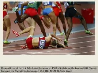
This knee study was centered over the mid shift of the femur. The proximal end of the tibia and fibula have been cutoff excluding the medial and lateral condyles of the tibia, an important part of a knee exam. In addition, the lateral knee projection is rotated and not a true lateral. What other important information is missing from this image? All Images must contain patient position markers. Be-Be markers are best, but electronic markers applied at the QC workstation are acceptable for indication of position. Remember electronic markers may not be used for left/right body side indication. Only lead left/right markers are acceptable. Standing Standing Or Upright Or Upright 54
Digital Image Processing • Many factors contribute to the creation of the digital projectional image. The primary factors that are controlled by the technologist are: • Collimation • kVp/mAs, overall dose • Number of views per plate • Anatomical Processing parameters • Centering of the image • The following examples all have problems with processing. 56
S-values should be more in the range of 150-250 for this exam. S-values under 100 are typically considered overexposed. CR images perform exactly opposite to that of film/screen. Typically the overexposed digital image will appear ‘light’ or in the case of this patella, ‘washed out’. Overexposed sunrise view 57
Window and level refers to the adjustment that can be made to the brightness and contrast of the processed image. For all Fuji CR images, this should be done at the Centricity QC workstation and NOT at the Fuji QC workstation. When making changes at the Fuji QC, the actual histogram is being modified and not the contrast and brightness. Here we see a foot that was modified at the Fuji QC. Notice the destruction of the grayscale especially surrounding the toes. 58
This is the same foot as the prior slide. Visualization of the tarsal's is now better, but the toes are still ‘burned out’. Once the histogram has been destroyed by over processing, no amount of window and level adjustment will salvage the image. 59
Can you determine the problem with this image? One problem led to the other. The technologist overexposed the image which caused it to become washed out. Then, a window and level fix was attempted at the Fuji QC workstation further eroding the grayscale. Lastly, the study was actually turned in for interpretation without any attempt at repeating. 60
Since the advent of digital projectional imaging, we have enjoyed working within a wider exposure latitude. However after a certain point, if the receptor does not receive enough dose, all the processing in the world will not produce an expectable image. Refer to the Super Technique chart for acceptable S-value ranges. This image is unacceptably noisy and must be repeated. 61
One of the factors that go into producing the final digital image, is how the acquisition device gathers the data off the imaging plate. Experience has shown that a single centered image will produce a better final image than multiple views on one plate. In addition, the Radiologist prefers to compare one view at a time per monitor during review. Exceptions to this rule are very small parts such as fingers or toes. 62
Congratulations! • You have completed the Orthopedic Imaging Bloopers module The Information Included in these Modules Represents the Basic Expectation of the Department for Imaging Quality. Click here to proceed to Orthopedic post test 63