Download
1 / 107
1.31k likes | 1.96k Vues
Failure Theories. Stress in machine components should be accurately computed. Designer must understand material limits to ensure a safe design. Design Factor. Factor of Safety (N) Suitable values depend on inherent danger, certainty of calculations, certainty of material properties, etc.

E N D
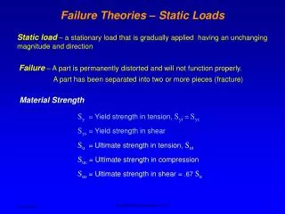
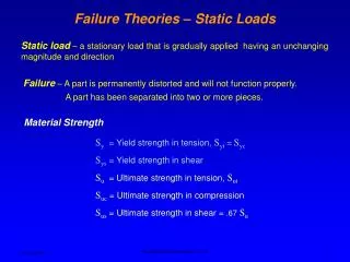
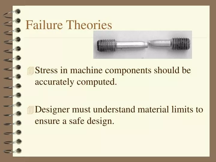
Failure Theories • Stress in machine components should be accurately computed. • Designer must understand material limits to ensure a safe design.
Design Factor • Factor of Safety (N) • Suitable values depend on inherent danger, certainty of calculations, certainty of material properties, etc.
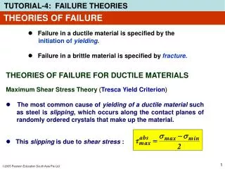
Static Stresses - Brittle Materials • Percent elongation < 5% • for parts in tension • for parts in compression • for parts with general stress
Ø4.00” R0.25” Ø5.00” R0.25” Example The Gray Cast Iron (Grade 40) cylinder carries an axial compressive load of 75,000 lbs and a torque of 20,000 in lbs. Compute the resulting design factor.
Static Stresses - Ductile Materials • Percent elongation > 5% • Distortion Energy Theory • Define von Mises Stress • For nominal stress • For localized stress
Static Stresses - Ductile Materials • Percent elongation > 5% • Maximum Shear Stress Theory • For nominal stress • For localized stress
450 5000 lbs Example Specify a diameter for the middle portion of the rod, if it is to be made from AISI 1040-hot rolled steel.
400 lb 200 lb 20” 14” Example For the seat support shown, specify a standard structural tube to resist static loads shown. The tube has properties similar to AISI 1020 hot-rolled steel. Use a design factor of 3.
salt smean Repeated Loads
1.25” 0.1” R .75” 1” Example The notched bar is machined from AISI 1020 steel. This bar is subjected to a load that varies from 2000 lb to 3000 lb. Determine the mean and alternating nominal stresses.
Motor Alternating Stress, sa Endurance Strength, sn 108 107 106 105 103 104 Cycles to Failure, N (log) Fatigue Strength • R.R. Moore Test
Endurance Strength • sn = Endurance strength • Listed in tables • If no information is available, use • sn 0.5 su (Steel) • sn 0.4 su (Aluminum)
Adjusted Endurance Strength • The data from the standard R.R. Moore test is adjusted for a particular application. • sn’ = Adjusted endurance strength = (Cs) (Cm) (Cst) (CR) (sn)
Size and Stress Type Factors • Cs = Size Factor • D< 0.4 in Cs = 1.0 • 0.4 < D 2.0 in Cs = (D/0.3)-0.068 • 2.0 < D 10.0 in Cs = D-0.19 For rectangular sections, D=.808(h b)1/2 • Cst = Stress Type Factor • = 1.0 for bending • = 0.80 for axial tension • = 0.50 for torsion
Material and Reliability Factor • Cm = Material Factor • = 1.0 for wrought steel • = 0.80 for cast steel • = 0.70 for cast iron • CR = Reliability Factor • 50% CR = 1.0 • 90% CR = 0.90 • 99% CR = 0.81 • 99.9% CR = 0.75
1.25” 0.1” R .75” 1” Example The notched bar is machined from AISI 1020 steel. This bar is subjected to a load that varies from 2000 lb to 3000 lb. Determine the endurance limit of the material.
Repeated Stresses - Ductile Materials • Distortion Energy Theory • Define repeated von Mises Stress • Solderberg criterion
Repeated Stresses - Ductile Materials • Maximum Shear Stress Theory • ssy = 0.5 sy • s’sn = 0.5 sn
1.25” 0.1” R .75” 1” Example The notched bar is machined from AISI 1020 steel. This bar is subjected to a load that varies from 2000 lb to 3000 lb. Comment on the robustness of the design.
48” Example Comment on the robustness of a 1-1/4” round bar made from AISI 1213 C-D steel. It carries a constant tensile load of 1500 lbs, a bending load that varies from 0 to 800 lbs at the senter of the 48” length and a constant torque of 1200 in lbs.
Shafts • Connect power transmission components. • Inherently subjected to transverse loads and torsion.
Wt Wr T Shaft Forces • Gears As before
Ftight D T Fslack = 0 Shaft Forces • Chains
Shaft Forces • V-belts Ftight D T Fslack
Shaft Forces • Flat belts Ftight D T Fslack
Material Properties • For steady load (torsion) sys=.5sy • For fatique load ( bending) sn’=cs cR sn cT = 1 (bending) cm = 1 (wrought steel)
Stress Concentrations • Keyseats • Sled Runner Kt = 1.6 • Profile Kt = 2.0 • Woodruff Kt = 1.5
Stress Concentrations • Shoulders • Sharp, Bearing (r/d .03) Kt = 2.5 • Round, Gear Bore (r/d .17) Kt = 1.5 • Grooves • Retaining Rings Kt = 1.5 Try not to let Kt’s overlap. Leave .10 - .15” between
Strength Analysis • Bending stress • Torsion stress For round sections For round sections
Strength Analysis • Mohr’s circle and Solderberg • Suggested Design Factors: • N=2 smooth operation • N=3 typical industrial operation • N=4 shock or impact loading
Minimum Acceptable Diameter • The designer must size the shaft. • Solve for appropriate diameters
Example Determine a suitable diameter for a shaft made from AISI 1144 OQT 1000. It is subjected to a reversing bending moment of 3000 ft lbs and a steady torque of 1800 ft lbs. The shaft has a profile keyway.
Example The shaft shown is part of a grain drying system • At A, a 34 lb. propeller-type fan requires 12 hp when rotating at 475 rpm. • A flat belt pulley at D delivers 3.5 hp to a screw conveyor handling the grain. • All power comes to the shaft through the v-belt at C. Using AISI 1144 cold drawn steel, determine the minimum acceptable diameter at C.
E B D A C 12” 4” 10” 10” 150 Sheave C Sheave D Example
Shafts Accessories • Components used to securely mount power transmitting elements on a shaft. • Axial • Rotational
Keys • Allow torque to be transferred from a shaft to a power transmitting element (gear, sprocket, sheave, etc.)
H W L Key Design • Use a soft, low strength material (ie, low carbon steel) • Standard size H=W=1/4 D • Design length based on strength
H W Shaft Dia. (in) W (in) T S Standard Key Sizes
Key Design • Key Shear • Failure Theory • Length
Example Specify a key for a gear (grade 40, gray cast iron) to be mounted on a shaft (AISI 1144, hot rolled) with a 2.00 in. diameter. The gear transmits 21000 lb-in of torque and has a hub length of 4 in.
Retaining Rings • Also known as snap rings • Provides a removable shoulder to lock components on shafts or in bores. • Made of spring steel, with a high shear strength. • Stamped, bent-wire, and spiral-wound.
Retaining Ring Selection • Based on shaft diameter & thrust force
Set Screws • Setscrews are fasteners that hold collars, pulleys, or gears on shafts. • They are categorized by drive type and point style.
D d Pins • A pin is placed in double shear • Holds torsion and axial loads • Hole is made slightly smaller than the pin (FN1 fit)
Example Specify a pin for a gear (grade 40, gray cast iron) to be mounted on a shaft (AISI 1144, hot rolled) with a 2.00 in. diameter. The gear transmits 21000 lb-in of torque and has a hub length of 4 in.
Roll Pins • Easier disassembly
Collars • Creates a shoulder on shaft without increasing stock size. • Held with either set screw or friction (clamped)
Mechanical Couplings • Couplings are used to join two shafts • Rigid couplings are simple and low cost. But they demand almost perfect alignment of the mating shafts. • Misalignment causes undue forces and accelerated wear on the shafts, coupling, shaft bearings, or machine housing.