Download
1 / 11
790 likes | 2.13k Vues
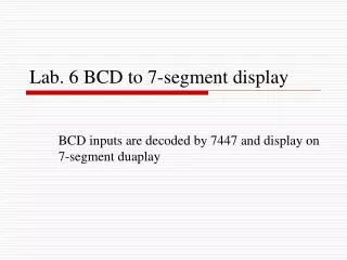
BCD to 7-Segment Display . Introduction. Digital Decoder IC, is a device which converts one digital format into another and one of the most commonly used device for doing this is called the Binary Coded Decimal (BCD) to 7-Segment Display Decoder.

E N D
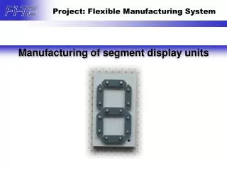
Introduction • Digital Decoder IC, is a device which converts one digital format into another and one of the most commonly used device for doing this is called the Binary Coded Decimal (BCD) to 7-Segment Display Decoder. • 7-segmentLED (Light Emitting Diode) or LCD (Liquid Crystal Display) type displays, provide a very convenient way of displaying information or digital data in the form of numbers, letters or even alpha-numerical characters. • Typically 7-segment displays consist of seven individual coloured LED's (called the segments), within one single display package. In order to produce the required numbers or HEX characters from 0 to 9and A to F respectively, on the display the correct combination of LED segments need to be illuminated and BCD to 7-segment Display Decoderswill be used.
Two important types of 7-segment LED digital display. • The Common Cathode Display (CCD) – In the common cathode display, all the cathode connections of the LED's are joined together to logic "0" or ground. The individual segments are illuminated by application of a "HIGH", logic "1" signal to the individual Anode terminals. • The Common Anode Display (CAD) – In the common anode display, all the anode connections of the LED's are joined together to logic "1" and the individual segments are illuminated by connecting the individual Cathode terminals to a "LOW", logic "0" signal.
Common Cathode and Common Anode Format • Electrical connection of the individual diodes for a common cathode display and a common anode display and by illuminating each light emitting diode individually, they can be made to display a variety of numbers or characters
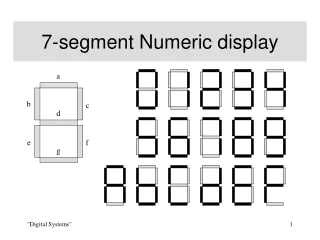
7-Segment Display Format Truth Table for a 7-segment display
It can be seen that to display any single digit number from 0 to 9 or letter from A to F, we would need 7 separate segment connections plus one additional connection for the LED's "common" connection. Also as the segments are basically a standard light emitting diode, the driving circuit would need to produce up to 20mA of current to illuminate each individual segment and to display the number 8, all 7 segments would need to be lit resulting a total current of nearly 140mA, (8 x 20mA). • Obviously, the use of so many connections and power consumption is impractical for some electronic or microprocessor based circuits and so in order to reduce the number of signal lines required to drive just one single display, display decoders such as the BCD to 7-Segment Display Decoder and Driver IC's are used instead.
Binary Coded Decimal • Binary Coded Decimal (BCD or "8421" BCD) numbers are made up using just 4 data bits (a nibble or half a byte) similar to the Hexadecimal number, but unlike hexadecimal numbers that range in full from 0 through to F, BCD numbers only range from 0 to 9, with the binary number patterns of 1010 through to 1111 (A to F) being invalid inputs for this type of display and so are not used as shown below.
BCD to 7-Segment Display Decoders • A binary coded decimal (BCD) to 7-segment display decoder such as the TTL 74LS47 or 74LS48, have 4 BCD inputs and 7 output lines, one for each LED segment. This allows a smaller 4-bit binary number (half a byte) to be used to display all the denary numbers from 0 to 9 and by adding two displays together, a full range of numbers from 00 to 99 can be displayed with just a single byte of 8 data bits.
An example of the 4-bit BCD input ( 0100 ) representing the number 4 is given below.
In practice current limiting resistors of about 150Ω to 220Ω would be connected in series between the decoder/driver chip and each LED display segment to limit the maximum current flow. Different display decoders or drivers are available for the different types of display available, e.g. 74LS48 for common-cathode LED types, 74LS47 for common-anode LED types, or the CMOS CD4543 for liquid crystal display (LCD) types.
Thanks For Your Patience All the best for exams