Download
1 / 37
380 likes | 842 Vues
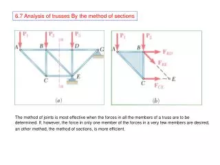
Atmospheric Correction of MODIS Data in the Visible to Shortwave Infrared: Method, Error Estimates and Validation Seminar, May 16 th 2007, NASA GSFC Eric F. Vermote & Svetlana Y. Kotchenova Department of Geography, University of Maryland, and NASA GSFC code 614.5 Surface Reflectance (MOD09)

E N D
Atmospheric Correction of MODIS Data in the Visible to Shortwave Infrared: Method, Error Estimates and Validation Seminar, May 16th 2007, NASA GSFC Eric F. Vermote & Svetlana Y. Kotchenova Department of Geography, University of Maryland, and NASA GSFC code 614.5
Surface Reflectance (MOD09) The Collection 5 atmospheric correction algorithm is used to produce MOD09 (the surface spectral reflectance for seven MODIS bands as it would have been measured at ground level as if there were no atmospheric scattering and absorption). Goal: to remove the influence of • atmospheric gases - NIR differential absorption for water vapor - EPTOMS for ozone • aerosols - own aerosol inversion Home page: http://modis-sr.ltdri.org Movie credit: Blue Marble Project (by R. Stöckli)Reference: R. Stöckli, E. Vermote,N. Saleous, R. Simmon, and D. Herring (2006) "True Color Earth Data Set Includes Seasonal Dynamics", EOS, vol. 87(5), 49-55. www.nasa.gov/vision/earth/features/blue_marble.html 2
Basis of the AC algorithm • The Collection 5 AC algorithm relies on • the use of very accurate (better than 1%) vector radiative transfer modeling of the coupled atmosphere-surface system • the inversion of key atmospheric parameters (aerosol, water vapor) 3
Vector RT modeling The Collection 5 atmospheric correction algorithm look-up tables are created on the basis of RT simulations performed by the 6SV (Second Simulation of a Satellite Signal in the Solar Spectrum, Vector) code, which enables accounting for radiation polarization. May 2005: the release of a β-version of the vector 6S (6SV1.0B) . . . . . . . . . . . . . . . . . . . . . . . . . . . . . . . . . . . . . . . . . . . . . . . . . . . . e x t e n s i v e v a l i d a t i o n a n d t e s t i n g . . . . . . . . . . . . . . . . . . . . . . . . . . . . . . . . . . . . . . . . . . . . . . . . . . . . . May 2007: the release of version 1.1 of the vector 6S (6SV1.1) 4
6SV Features • Spectrum: 350 to 3750 nm • Molecular atmosphere: 7 code-embedded + 6 user-defined models • Aerosol atmosphere: 6 code-embedded + 4 user-defined (based on components and distributions) + AERONET • Ground surface: homogeneous and non-homogeneous with/without directional effect (10 BRDF + 1 user-defined) • Instruments: AATSR, ALI, ASTER, AVHRR, ETM, GLI, GOES, HRV, HYPBLUE, MAS, MERIS, METEO, MSS, TM, MODIS, POLDER, SeaWiFS, VIIRS, and VGT 5
6SV Validation Effort • The complete 6SV validation effort is summarized in two manuscripts: • S. Y. Kotchenova, E. F. Vermote, R. Matarrese, & F. Klemm, Validation of a vector version of the 6S radiative transfer code for atmospheric correction of satellite data. Part I: Path Radiance, Applied Optics, 45(26), 6726-6774, 2006. • S. Y. Kotchenova & E. F. Vermote, Validation of a vector version of the 6S radiative transfer code for atmospheric correction of satellite data. Part II: Homogeneous Lambertian and anisotropic surfaces, Applied Optics, in press, 2007. 6
Effects of Polarization Example: Effects of polarization for the mixed (aerosol (from AERONET) + molecular) atmosphere bounded by a dark surface. The maximum relative error is more than 7%. 7
6SV Web page http://6S.ltdri.org 8
6SV Interface We provide a special Web interface which can help an inexperienced user learn how to use 6SV and build necessary input files. This interface also lets us track the number and location of 6SV users based on their IP addresses. 9
6SV Users (over the World) Total:898 users 10
6SV Users (Distribution per Country) 6SV e-mail distribution list:142 users 12
Vector 6S Monte Carlo (benchmark) Dave Vector SHARM (scalar) RT3 Coulson’s tabulated values (benchmark) Code Comparison Project (1) All information on this project can be found athttp://rtcodes.ltdri.org 13
Code Comparison Project (2) • Goals: • to illustrate the differences between individual simulations of the codes • to determine how the revealed differences influence on the accuracy of atmospheric correction and aerosol retrieval algorithms Example: Results of the comparison for a molecular atmosphere with τ = 0.25. 14
Key atmospheric parameters Vector 6S LUTs AC algorithm coarse resolution meteorological data MODIS calibrated data Input Data for Atmospheric Correction • surface pressure • ozone concentration • column water • aerosol optical thickness (new) Reference: Vermote, E. F. & El Saleous, N. Z. (2006). Operational atmospheric correction of MODIS visible to middle infrared land surface data in the case of an infinite Lambertian target, In: Earth Science Satellite Remote Sensing, Science and Instruments, (eds: Qu. J. et al), vol. 1, chapter 8, 123 - 153. 15
Error Budget (Collection 4) Goal: to estimate the accuracy of the atmospheric correction under several scenarios 16
Calibration Uncertainties We simulated an error of ±2% in the absolute calibration across all 7 MODIS bands. Results: The overall error stays under 2% in relative for all τaer considered. (In all study cases, the results are presented in the form of tables and graphs.) Table (example): Error on the surface reflectance (x 10,000) due to uncertainties in the absolute calibration for the Savanna site. 17
Uncertainties on Pressure and Ozone • The pressure error has impact on • molecular scattering (specific band) • the concentration of trace gases (specific band) • τaer (all bands) • The ozone error has impact on • the band at 550 nm (mostly) • the band at 470 nm the retrieval of τaer all bands 18
Impact of water vapor uncertainties (+/-0.2g/cm2) Uncertainties on Water Vapor • Retrieval of the column water vapor content: • if possible, from MODIS bands 18 (931-941 nm) and 19 (915 – 965 nm) by using the differential absorption technique. The accuracy is better than 0.2 g/cm2. • if not, from meteorological data from NCEP GDAS Table (example): Error on the surface reflectance (x 10,000) due to uncertainties in the water vapor content for the Semi-arid site. 19
Original approach: “dark and dense vegetation (DDV) technique” a linear relationship between ρVIS and ρNIR limitation to the scope of dark targets Current approach: a more robust “dark target inversion scheme” a non-linear relationship derived using a set of 40 AERONET sites representative of different land covers can be applied to brighter targets Retrieval of Aerosol Optical Thickness 20
Uncertainties on the Aerosol Model In the AC algorithm, an aerosol model is prescribed depending on the geographic location. We studied an error generated by the use of an improper model. Prescribed: urban clean Additional: urban polluted, smoke low absorption, smoke high absorption The choice of the aerosol model is critical for the theoretical accuracy of the current product (in particular, for the accuracyof optical thickness retrievals). 21
Collection 5 Aerosol Inversion Algorithm Pioneer aerosol inversion algorithms for AVHRR, Landsat and MODIS (Kaufman et al.) (the shortest λ is used to estimate the aerosol properties) • Refined aerosol inversion algorithm • use of all available MODIS bands (land + ocean, e.g. 412nm as in Deep Blue) • improved LUTs • improved aerosol models based on the AERONET climatology • a more robust “dark target inversion scheme” using Red to predict the blue reflectance values (in tune with Levy et al.) • inversion of the aerosol model (rudimentary) 22
Example 1: RGB (670 nm, 550 nm, 470 nm) Top-of-atmosphere reflectance RGB (670 nm, 550 nm, 470 nm) Surface reflectance 23
490 nm 470 nm 443 nm 412 nm 0.5 0.2 0.4 Aerosol Optical Depth Example 1: Red (670 nm) Top-of-atmosphere reflectance 24
RGB (670 nm, 550 nm, 470 nm) Surface reflectance Example 2: AOT= 0.896 (7km x 7km) Model residual: Smoke LABS: 0.003082 Smoke HABS: 0.004978 Urban POLU: 0.04601 Urban CLEAN: 0.006710 RGB (670 nm, 550 nm, 470 nm) Top-of-atmosphere reflectance 25
RGB (670 nm, 550 nm, 470 nm) Surface reflectance Example 3: AOT= 0.927 (7km x 7km) Model residual: Smoke LABS: 0.005666 Smoke HABS: 0.004334 Urban POLU: 0.004360 Urban CLEAN: 0.005234 RGB (670 nm, 550 nm, 470 nm) Top-of-atmosphere reflectance 26
Overall Theoretical Accuracy Overall theoretical accuracy of the atmospheric correction method considering the error source on calibration, ancillary data, and aerosol inversion for 3 τaer = {0.05 (clear), 0.3 (avg.), 0.5 (hazy)}: The selected sites are Savanna (Skukuza), Forest (Belterra), and Semi-arid (Sevilleta). The uncertainties are considered independent and summed in quadratic. 27
Performance of the MODIS C5 algorithms To evaluate the performance of the MODIS Collection 5 algorithms, we analyzed 1 year of Terra data (2003) over 127 AERONET sites (4988 cases in total). Methodology: Subsets of MOD09 data processed using the standard surface reflectance algorithm comparison Reference data set Vector 6S Subsets L1B If the difference is within ±(0.005+0.05ρ), the observation is “good”. AERONET measurements (τaer, H2O, particle distribution) http://mod09val.ltdri.org/cgi-bin/mod09_c005_public_allsites_onecollection.cgi 28
Validation of MOD09 (1) Comparison between the MODIS band 1 surface reflectance and the reference data set. The circle color indicates the % of comparisons within the theoretical MODIS 1-sigma error bar: green > 80%, 65% < yellow <80%, 55% < magenta < 65%, red <55%. The circle radius is proportional to the number of observations. Clicking on a particular site will provide more detailed results for this site. 29
Validation of MOD09 (2) Example: Summary of the results for the Alta Foresta site. Each bar: date & time when coincident MODIS and AERONET observations are available The size of a bar: the % of “good” surface reflectance observations Scatter plot: the retrieved surface reflectances vs. the reference data set along with the linear fit results 30
Validation of MOD09 (3) In addition to the plots, the Web site displays a tablesummarizing the AERONET measurementand geometrical conditions, and shows browse images of the site. MOD09-SFC Percentage of good: band 1 – 86.62% band 5 – 96.36% band 2 – 94.13% band 6 – 97.69% band 3 – 51.30% band 7 – 98.64% band 4 – 75.18% Similar results are available for all MODIS surface reflectance products (bands 1-7). 31
Validation of MOD13 (NDVI) Comparison of MODIS NDVI and the reference data set for all available AERONET data for 2003. Globally, 97.11% of the comparison fall within the theoretical MODIS 1-sigma error bar (±(0.02 + 0.02VI)). green > 80%, 65% < yellow <80%, 55% < magenta < 65%, red <55% 32
Validation of MOD09 (EVI) Comparison of MODIS EVI and the reference data set for all available AERONET data for 2003. Globally, 93.64% of the comparison fall within the theoretical MODIS 1-sigma error bar (±(0.02 + 0.02VI)). green > 80%, 65% < yellow <80%, 55% < magenta < 65%, red <55% 33
Generalization of the approach for downstream product (e.g., Albedo) 34
Collection 5:TerraAqua Surface Reflectance Daily L2G Global 250 m MOD09GQ MYD09GQ Surface Reflectance Daily L2G Global 500 m and 1 km MOD09GA MYD09GA Surface Reflectance 8-Day L3 Global 250 m MOD09Q1 MYD09Q1 Surface Reflectance 8-Day L3 Global 500 m MOD09A1 MYD09A1 Surface Reflectance Quality Daily L2G Global 1km MOD09GST MYD09GST Surface Reflectance Daily L3 Global 0.05Deg CMG MOD09CMG MYD09CMG Availability: February 2000 through December 2000, Terra only Collection 5 Description:http://modis-sr.ltdri.org * CMG – Climate Modeling Grid 35 5
Land Cover Thermal Anomalies BRDF/Albedo Burned Areas LAI/FPAR VI Snow Cover MOD09 Applications Surface Reflectance 36
Thanks! Thank you for your attention! Questions:6S@ltdri.org & mod09@ltdri.org 37