Download
1 / 17
170 likes | 334 Vues
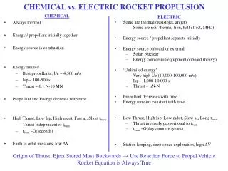
Electric Propulsion Continued. The "jet" or exhaust power (P jet ) of any thruster is: P jet = 1/2 g c I sp F Thus, for a situation where we wish to fix the thrust at a constant value, as specific impulse increases, the jet power must also increase.

E N D
The "jet" or exhaust power (Pjet) of any thruster is: Pjet = 1/2 gc Isp F Thus, for a situation where we wish to fix the thrust at a constant value, as specific impulse increases, the jet power must also increase. Jet power is in turn a function of the total "bus" electric power (Pe) and the overall efficiency (h) of converting electric power into jet power: Pjet = Pe h ..The mass of the electric power system (as well as power conditioning and thrusters) is proportional to the total "bus" electric power: Mpower = a Pe where a is the overall system specific mass (typically in kg/kW electric). Finally, .. M0 / Mb = exp (DV / gc Isp) The propellant mass (Mp) is simply the difference between M0 and Mb: Mp = M0 - Mb
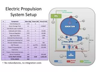
Designing Electric Propulsion Path A: Power Source Based on Chosen Thruster and Mission Specify Mission – Select Thruster – Select Power Source Design Thermal Mgmt System – Design Power Conditioning System – Assess Performance Path B: Power Source Based on What is Available from Spacecraft Specify Mission –Select Power Source - Select Thruster – Design Power Conditioning - Design Thermal Mgmt System –System – Assess Performance
Optimum Specific Impulse Courtesy: Robert.H. Frisbee, JPL http://www.islandone.org/APC/Electric/impulse.gif
System Analysis mdotp, mass flow rate of propellant Thrust or Jet Power: : Initial mass Required source power System inert mass Specific mass of propulsion system (Kg/W) Specific power of propulsion system (W/Kg)
If thrust duration (assuming constant thrust) is where is final mass achieving
Propulsion system mass per unit of jet power: Jet-specific mass Optimal exhaust speed: Where k ~ 1
If is too high, or the allowable thrust time is too low, optimum speed may be less than that from chemical rockets. May still use electric propulsion for missions with electric power supply; Primary electric propulsion will not benefit from power system sharing until it is a large scale mission with many MW of power Possible uses -> station-keeping (no benefit to impulsive thrust) -> lifting large structures (low g; continuous thrust) -> Electric primary propulsion needs > 1000s to compete with modern chemical system (450s)
Specific Impulse Ranges Electrothermal: 500 – 1000 s Electromagnetic: 1000 – 7000s Electrostatic: 2000 – 100,000s
Electromagnetic Propulsion Electromagnetic force per unit volume on a gas carrying current in a magnetic field magnetic induction field in gas (Tesla) Electric current density In gas (A/m2) N/m3
Electromagnetic Propulsion Systems Unsteady vs. Steady Self-field vs. Applied Field. Self Field: Discharge currents whose own magnetic fields are high enough for efficient thruster performance without needing external applied magnetic fields. High power (MW) Available in short pulses from capacitor bank: unsteady operation.
Z-Pinch and q-Pinch Engines z -Pinch Engine: Current has component parallel to axis of symmetry. q-Pinch Engine: Current is in azimuthal direction In both, current and self-fields combine to implode (pinch) plasma Gives 10 – 40 km/s velocity. (See Humble, Fig. 9.11)
Pulsed Inductive Thruster Coil and plasma currents are azimuthal; magnetic field is radial. Plasma accelerates parallel to axis of symmetry Ablation-supplied propellant for pulsed operation. See Fig. 9.12, Humble. www.islandone.org/ APC/Electric/16.html http://www.airpower.maxwell.af.mil/airchronicles/aureview/1973/Nov-Dec/Baty3.jpg
Pulsed-Plasma Microthruster www.mae.cornell.edu/ campbell/mppt/mppt.htm
Magnetoplasmadynamic Thrusters Discharge current interacts with its own magnetic field to accelerate flow axially and radially. At low particle density, electromagnetic force density greatly exceeds pressure gradients in the gas. “J × B Lorentz body force compresses and accelerates a quasi-neutral plasma along the central axis. Because self-induced magnetic field is only significant at very high power, low power MPD thrusters often resort to an externally applied magnetic field in order to enhance the acceleration process (applied field MPD thrusters).” http://fluid.ippt.gov.pl/sbarral/pics/mpd_thruster.jpg
Hall Effect Applied magnetic fields increase electromagnetic forces in plasma. They also force current to flow in spiral paths, increasing the total voltage. Hall effect is evident in electromagnetic thrusters at low particle density. Xenon with radial magnetic field and axial current flow from an upstream anode: Stationary Plasma thruster. 5-20 KW; Isp 1500 – 2000 s; high efficiency. Axial current across radial magnetic field generates azimuthal electron flow. Internal Hall electric field in axial direction transmits axial e-mag force on electron flow, to plasma ions. Charge-neutral device.