Download
1 / 44
460 likes | 678 Vues
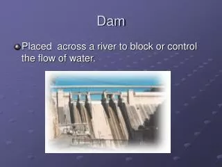
Formation of the Dam Body. For Concrete Gravity dams:. Low-heat cements to reduce shrinkage problem Concrete is placed in “ blocks ” “ Keyways ” are built between sections to make the dam act as a monolith. Upstream face. Upstream face. Keyways. Downstream face.

E N D
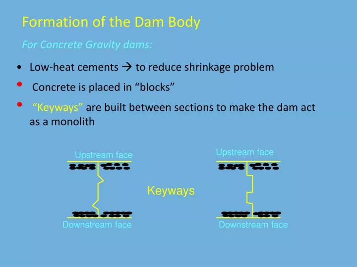
Formation of the Dam Body For Concrete Gravity dams: • Low-heat cements to reduce shrinkage problem • Concrete is placed in “blocks” • “Keyways”are built between sections to make the dam act as a monolith Upstream face Upstream face Keyways Downstream face Downstream face
“Waterstops”are placed near upstream face to prevent leakage Copper strip Copper strip Waterstops “Inspection galleries” permit access to the interior of concrete Dams and are needed for seepage determination, grouting operations and etc.
For Earth-fill dams • Constructed in multi-layer formation • (Layers: impervious, filter and outer) • First place the materials in layers of 50 cm and then compact these materials. • For high dams, horizontal berms are constructed to enhance slope stability • Protect the upstream face of dam against wave action • (i.e., concrete or riprap) • Protect the downstream face against rainfall erosion • (i.e., planting grass or riprap)
Cross section of typical earth dams 1 on 2.5 1 on 2 Silt Sandy gravel Silt clay (a) Simple zoned embankment 1 on 2.5 1 on 2.5 Clay core Silt Rock-fill toe Silt Pervious strata Transition zone Pervious foundation (b) Earth dam with core extending to impervious foundation
Cross section of typical earth dams 1 on 2 1 on 3.1 1 on 3.8 Clay blanket Sandy gravel Silt Silt clay Pervious material Concrete cutoff wall (c) Earth dam on pervious material
For Rock-fill dams: • Core and filter zones are similarly constructed as the earth dam • Due to heavy rocks on the sides, these dams • have steeper slopes • have less materials • are economic • Construction period is shorter and easy to increase the crest elevation • Width of dam crest: There are two traffic lanes • Elevation of dam crest: There is no overtopping during design flood • Freeboard: See the table for recommendations
Select Compacted Rock Rolled Medium Size Rock 1.3 1.3 1 1 Coarse Dumped Rock Reinforced Concrete Membrane Cutoff wall (a) Impermeable face Cross-section of typical Rock-fill dams Graded transition sections 1.4 1.4 1 1 Clay core Dumped or Rolled rock Dumped Rock Rolled rock (0.2m) (1.5m) Grout curtain (b) Impermeable earth-core
GRAVITY DAMS Recep YURTAL Ç.Ü. İnş.Müöl.
Concrete Gravity Dams Resist the forces by their own weight Ç.Ü. İnş.Müöl.
Concrete Gravity Dams Ç.Ü. İnş.Müöl.
Concrete Gravity Dams Ç.Ü. İnş.Müöl.
Concrete Gravity Dams Ç.Ü. İnş.Müöl.
Concrete Gravity Dams • Why & Whereweprefered? • Sağlam ve geçirimsizliği sağlanabilecek yeterli kalınlıkta kaya temellerin uygun bir derinlikte bulunduğu orta genişlikteki vadilerde • Yeterli miktarda ve istenen özellikte agrega malzemesinin bulunduğu, çimento naklinin ekonomik olduğu yerlerde • Büyük taşkın debilerinin baraj gövdesi üzerinden mansaba aktarılması gereken durumlarda • Baraj üzerinden bir ulaşım yolu geçirilmesi gereken durumlarda tercih edilir • Savaş ve sabotaja karşı daha dayanıklı olması da ayrıca bir tercih nedeni olabilir. Ç.Ü. İnş.Müöl.
Concrete Gravity Dams • Types: • StraightGravityDams • ArchGravityDams • Baraj ekseni, iki yamaç arasındaki en kısa bağlantıyı sağlayacak şekilde bir doğru ile birleştirilir. • Temel kayasının yapısına, derzlere veya emniyet ihtiyacına bağlı olarak kavisli de yapılabilir. Ç.Ü. İnş.Müöl.
Concrete Gravity Dams • Design Criteria: • En uygun kesit, etki eden en önemli dış kuvvet olan haznedeki hidrostatik su basıncı dağılımına uyum sağlayan, tabana doğru genişleyen üçgen kesit seçilir. Üçgenin tepesi genellikle haznedeki en yüksek su seviyesidir. • Memba yüzeyi düşey veya %10 ‘u geçmeyecek şekilde eğimli yapılır. • Baraj boş haldeyken çekme gerilmelerini önlemek, dolu haldeyken kayma ve devrilme emniyetini artırmak için yüksek barajlarda memba yüzeyi genellikle eğimli planlanır. • Üçgenin tepe kısmında, duvar kalınlığını artırmak, yamaçlar arası ulaşımı sağlamak gibi nedenlerle dikdörtgen kesitli bir başlık bulunur. Ç.Ü. İnş.Müöl.
Concrete Gravity Dams Design Criteria: Ç.Ü. İnş.Müöl.
H b Concrete Gravity Dams Design Principles: • Ağırlık barajı hesaplarında üçgen profil gözönüne alınır. • Üçgen kesitin minimum boyutları, barajın kendi ağırlığı, hidrostatik su basıncı ve taban su basıncının etki ettiği normal yükleme durumunda çekme gerilmeleri meydana gelmeyecek şekilde belirlenir. • Bunun için: Ç.Ü. İnş.Müöl.
Concrete Gravity Dams • For the dam dimensions: • Check out the safety for • Overturning • Shear & sliding • Bearing capacity of foundation • No tensile stresses are allowed in the dam body
B Overturning Check 1/md H Ç.Ü. İnş.Müöl.
B Overturning Check H Ç.Ü. İnş.Müöl.
B Overturning Check H Ç.Ü. İnş.Müöl.
B Overturning Check H Ç.Ü. İnş.Müöl.
B Overturning Check H Ç.Ü. İnş.Müöl.
B Overturning Check H Ç.Ü. İnş.Müöl.
B Sliding Check 1/md H Ç.Ü. İnş.Müöl.
B Sliding Check H Ç.Ü. İnş.Müöl.
B Sliding Check H Ç.Ü. İnş.Müöl.
B Sliding Check H Ç.Ü. İnş.Müöl.
B Sliding Check 1/md H Ç.Ü. İnş.Müöl.
Bearing Capacity Check 1/md H Ç.Ü. İnş.Müöl.
3.5.1FORCES ON GRAVITY DAMS Free body diagram showing forces acting on a gravity dam
The following loads should be considered: A) WEIGHT (WC): Dead load and acts at the centroid of the section B) HYDROSTATIC FORCES: Water in the reservoir + tailwater causes Horizontal Hu Hd & Vertical Fh1v Fh2v C) UPLIFT FORCE (Fu): acts under the base as:
D) FORCE OF SEDIMENT ACCUMULATION (Fs): Determined by the lateral earth pressure expression • where • Fs : the lateral earth force per unit width, • γs : the submerged specific weight of soil, • hs : the depth of sediment accumulation relative to reservoir bottom elevation, • θ : the angle of repose. • This force acts at hs /3 above the reservoir bottom.
E) ICE LOADS (Fi): considered in cold climate Ice force per unit width of dam (kN/m) can be determined from the following table:
F) EARTHQUAKE FORCE (Fd): Acting horizontally and vertically at the center of gravity k (earthquake coefficient): Ratio of earthquake acceleration to gravitational acceleration.
G) DYNAMIC FORCE (Fw) : In the reservoir, induced by earthquake as below Acts at a distance 0.412 h1 from the bottom • Fw : the force per unit width of dam • C : constant given by • θ’ : angle of upstream face of the dam from vertical (oC) • For vertical upstream face C = 0.7 '
H) FORCES ON SPILLWAYS (∑F): Determined by using momentum equation btw two successive sections: • ρ : the density of water • Q : the outflow rate over the spillway crest • ΔV: the change in velocity between sections 1 and 2 (v2-v1) • Momentum correction coefficients can be assumed as unity.
I) WAVE FORCES : Considered when a long fetch exists LOADING CONDITIONS: • Usual loading B &Temperature Stresses at normal conditions + C + A + E + D • Unusual loading B & Temperature Stresses at min. at full upstream level + C + A +D • Severe loading Forces in usual loading + earthquake forces
3.5.2 STABILITY CRITERIA • Dam must be safe against • (1) Overturning for all loading conditions resisting moments overturning moments Safety factor: • F.SO 2,0 (usual loading) • F.SO 1,5 (unusual loading)
STABILITY CRITERIA • (2) Sliding over any horizontal plane • f = friction coef. btw any two planes Safety factor: • FSS 1,5 (usual loading ) • FSS 1,0 (unusual or severe loading)
STABILITY CRITERIA • (3) Shear and sliding together A : Area of shear plane (m²) τs : Allowable shear stress in concrete in contact with foundation Safety factor: • FSss 5,0 (usual loading) • FSss 3,0 (unusual or severe loading)
STABILITY CRITERIA • (4) Between foundation and dam contact stresses (σ) > 0 at all points There are two cases for the base pressure:
B DAM BASE Ph Pt e ΣV Base Pressure Check • CASE 1: e B/6 Pt s Ph s Ç.Ü. İnş.Müöl.
B DAM BASE Pt e Base Pressure Check CASE 2: e > B/6 Pt s ΣV Ç.Ü. İnş.Müöl.