Download
1 / 44

E N D
FRACTURE METE 327 Fall 2008 METE 327 Physical Metallurgy Copyright 2008 Loren A. Jacobson 5/16/08
OUTLINE ●What is Fracture? ●The Griffith Equation ●The Orowan Modification ●Statistics—Weibull Distribution ●Examples – 35 MgO samples – Wesgo Al95 Alumina – Plaster ●Transition to Fracture Mechanics METE 327 Physical Metallurgy Copyright 2008 Loren A. Jacobson 5/16/08
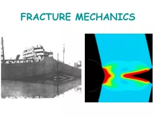
What is Fracture? ●Most Fracture failures are “unexpected” failures ●What is an “unexpected” failure? ●The expected load carrying capacity of a structural member is its yield strength times its cross sectional area ●The presence of a flaw can change this ●The following approach was proposed by Griffith in 1920 METE 327 Physical Metallurgy Copyright 2008 Loren A. Jacobson 5/16/08
The Griffith Equation Uniform Stress, σ σ A plate of unit thickness has a through crack of length 2c. The crack has a surface energy of 4cγγ, where γγ is the energy required to create a unit area of new surface. The total energy content of the plate, under the applied stress is σ σ energy is reduced by the volume of material in the cylinder of radius c. σ2/E. Now, if the crack extends δ δ 2 c 2/E. Due to the crack, this Uniform Stress, σ σ This energy is π a small amount, δ δ , then the strain energy is further reduced by an amount (π The additional surface is 4 δ δ , so the additional surface energy is 4 δ δ γ γ. π c2σ (π c2σ σ2/E)δ δ. METE 327 Physical Metallurgy Copyright 2008 Loren A. Jacobson 5/16/08
The Griffith Equation (cont) We set these two quantities equal to one another So, 4δ γ stress at which the crack will propagate is: δ γ = 2π π cδ σ δ σ2/E. The deltas cancel, and so the And that is the Griffith Equation. METE 327 Physical Metallurgy Copyright 2008 Loren A. Jacobson 5/16/08
Orowan Modification For ductile materials, Orowan modified the Griffith equation in 1952 by substituting two terms for γ γ : γ γ s is the surface energy, and γ γ pis the plastic energy. γ γ s is about 1-2 J/m2, and γ γ p is 100- 1000 J/m2, so we can write: Before we use this equation as a lead-in to Fracture Mechanics, some additional aspects of brittle fracture: Statistical nature–Weibull Distribution METE 327 Physical Metallurgy Copyright 2008 Loren A. Jacobson 5/16/08
The Weibull Distribution ●Probability of failure, S = n/(N+1) where N is the total number of specimens and n is the order number in increasing strength ● Then Si = (1-e -Bi) where Bi is called the risk of rupture, and Bi = ((σi – σu)/σo)m ● Where σi is the ith specimen strength, σu is the so-called “zero strength” , σo is a normalizing factor and m is the flaw density exponent. ●Sometimes B is multiplied by a dimensionless volume to account for a possible size effect. METE 327 Physical Metallurgy Copyright 2008 Loren A. Jacobson 5/16/08
Weibull Distribution (cont.) ●Take the double logarithm of both sides and plot log log S vs. log (σi – σu) for different values of σu. ● The best value of σu will give a straight line of slope m. ●A computer program was written to find the best fit using different choices of σu . (minimize the sum of the deviations squared from a line). METE 327 Physical Metallurgy Copyright 2008 Loren A. Jacobson 5/16/08
35 MgO Strength Values in increasing order 1 2 3 4 5 6 7 8 9 10 11 12 13 14 15 16 17 18 23700 23950 25050 25800 25950 26900 26950 27050 27800 28050 28150 28200 28300 28400 28550 28800 29000 29300 19 20 21 22 23 24 25 26 27 28 29 30 31 32 33 34 35 29350 29400 29450 29600 29700 30400 30500 30850 30950 31000 31200 31400 31450 31700 31750 31900 34400 METE 327 Physical Metallurgy Copyright 2008 Loren A. Jacobson 5/16/08
METE 327 Physical Metallurgy Copyright 2008 Loren A. Jacobson 5/16/08
METE 327 Physical Metallurgy Copyright 2008 Loren A. Jacobson 5/16/08
METE 327 Physical Metallurgy Copyright 2008 Loren A. Jacobson 5/16/08
METE 327 Physical Metallurgy Copyright 2008 Loren A. Jacobson 5/16/08
METE 327 Physical Metallurgy Copyright 2008 Loren A. Jacobson 5/16/08
METE 327 Physical Metallurgy Copyright 2008 Loren A. Jacobson 5/16/08
Fracture Mechanics Fracture Mechanics Earlier we derived the Orowan modification to the Griffith equation, to take into account plastic deformation as an energy absorbing mechanism in crack propagation: absorbing mechanism in crack propagation: Earlier we derived the Orowan modification to the Griffith equation, to take into account plastic deformation as an energy George Irwin, in the early 1960's proposed a quantity G, the strain energy release rate, or the crack extension force, giving an equation for the fracture stress in terms of G: equation for the fracture stress in terms of G: George Irwin, in the early 1960's proposed a quantity G, the strain energy release rate, or the crack extension force, giving an METE 327 Physical Metallurgy Copyright 2008 Loren A. Jacobson 5/16/08
but, γp and Gc are difficult quantities to measure, so Irwin proposed the stress intensity factor, stress and a is the half crack length. It is similar to a stress concentration factor, and can be easily measured. K has somewhat unusual units of Mpa-m1/2 or KSI-in1/2. Now, and K2 = GE so, substituting we get: and K2 = GE so, substituting we get: and K2 = GE so, substituting we get: but, γp and Gc are difficult quantities to measure, so Irwin proposed the stress intensity factor, stress and a is the half crack length. It is similar to a stress concentration factor, and can be easily measured. K has somewhat unusual units of Mpa-m1/2 or KSI-in1/2. Now, somewhat unusual units of Mpa-m1/2 or KSI-in1/2. Now, where σ is the where σ is the where σ is the proposed the stress intensity factor, stress and a is the half crack length. It is similar to a stress or, more generally, where α includes a number of geometrical factors: METE 327 Physical Metallurgy Copyright 2008 Loren A. Jacobson 5/16/08
The Critical Stress Intensity Factor ● Usually expressed as KIc, and it is a true material property ●There is a minimum thickness in order to be certain that plane strain conditions exist – Thickness, B = 2.5(KIc/σo)2 is the critierion where σo is the 0.2% offset yield strength ●There can be no assurance that a test will be valid until it is performed ●An estimate of thickness can be made using an expected value of KIc METE 327 Physical Metallurgy Copyright 2008 Loren A. Jacobson 5/16/08
Crack Opening Modes I II III II III I METE 327 Physical Metallurgy Copyright 2008 Loren A. Jacobson 5/16/08
METE 327 Physical Metallurgy Copyright 2008 Loren A. Jacobson 5/16/08
Types of Test Specimens METE 327 Physical Metallurgy Copyright 2008 Loren A. Jacobson 5/16/08
Types of Test Specimens (cont.) METE 327 Physical Metallurgy Copyright 2008 Loren A. Jacobson 5/16/08
Different types of load-displacement curves METE 327 Physical Metallurgy Copyright 2008 Loren A. Jacobson 5/16/08
Explanation of Curves ●Type I—typical of most ductile metals. Line OP is at 5% lower slope than tangent OA. PS = PQ – If x1 is more than ¼ of xS then material is too ductile ●Type II—shows a pop-in, but must meet the maximum ductility criterion—PQ is max load ●Type III—shows a complete pop-in instability and is characteristic of a brittle “elastic” material ● PQ is used to calculate KQ and if the thickness is greater than calculated for plane strain, then KQ equals KIC. METE 327 Physical Metallurgy Copyright 2008 Loren A. Jacobson 5/16/08
Example: Thin-Wall Pressure Vessel METE 327 Physical Metallurgy Copyright 2008 Loren A. Jacobson 5/16/08
Thin-Wall Pressure Vessel ●Material: Ti 6Al 4V, Hoop Stress = 360 MPa ● KIc = 57 Mpa m1/2 ● σo = 900 Mpa ●Crack oriented as shown above ●For this type of loading and geometry: 2 = (1$.21aπσ2)/Q ● KI ●a =Surface crack depth METE 327 Physical Metallurgy Copyright 2008 Loren A. Jacobson 5/16/08
Thin-Wall Pressure Vessel ● For a wall thickness of 12 mm, and σ/σ0 = 0.4 ●If 2c=2a then Q = 2.35 ● Then the critical crack size, ac = 15.5 mm ●The critical crack depth is greater than the wall thickness and the vessel will “leak before burst” ● However if a/2c = 0.05, Q = 1 and ac = 6.6 mm ●This is less than the wall thickness ●So, vessel will burst! METE 327 Physical Metallurgy Copyright 2008 Loren A. Jacobson 5/16/08
METE 327 Physical Metallurgy Copyright 2008 Loren A. Jacobson 5/16/08
METE 327 Physical Metallurgy Copyright 2008 Loren A. Jacobson 5/16/08
METE 327 Physical Metallurgy Copyright 2008 Loren A. Jacobson 5/16/08
Steel, compression side Crack growth by fatigue Pre-existing crack 1" Steel, tension side METE 327 Physical Metallurgy Copyright 2008 Loren A. Jacobson 5/16/08
METE 327 Physical Metallurgy Copyright 2008 Loren A. Jacobson 5/16/08
METE 327 Physical Metallurgy Copyright 2008 Loren A. Jacobson 5/16/08
METE 327 Physical Metallurgy Copyright 2008 Loren A. Jacobson 5/16/08
METE 327 Physical Metallurgy Copyright 2008 Loren A. Jacobson 5/16/08
METE 327 Physical Metallurgy Copyright 2008 Loren A. Jacobson 5/16/08
Influence of corrosive environment METE 327 Physical Metallurgy Copyright 2008 Loren A. Jacobson 5/16/08
METE 327 Physical Metallurgy Copyright 2008 Loren A. Jacobson 5/16/08
METE 327 Physical Metallurgy Copyright 2008 Loren A. Jacobson 5/16/08
METE 327 Physical Metallurgy Copyright 2008 Loren A. Jacobson 5/16/08
Periodic Overloads Notch Root Extent of flat fracture METE 327 Physical Metallurgy Copyright 2008 Loren A. Jacobson 5/16/08
Periodic Overloads ●The overload creates a larger plastic zone ●If applied infrequently, the residual stress does not build up to slow the crack propagation ●If applied to often, it causes a greater rate of crack propagation ●At an intermediate rate, the plastic zone, and hence the residual compressive stress, is present for more of the growth cycles METE 327 Physical Metallurgy Copyright 2008 Loren A. Jacobson 5/16/08
Plastic Zone Size rp = (1/2π)(σ2a/σ0 2) For a steel with a = 10 mm, σ = 400 Mpa σ0 = 1500 Mpa rp = 0.113 mm METE 327 Physical Metallurgy Copyright 2008 Loren A. Jacobson 5/16/08
METE 327 Physical Metallurgy Copyright 2008 Loren A. Jacobson 5/16/08