Download
1 / 46
490 likes | 656 Vues
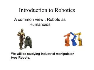
Introduction to Robotics. Review. Spectrum of robot control Reactive, deliberative Brief history of robotics Control theory Cybernetics AI Effectors and Actuators DC Motors. DC Motors. DC (direct current) motors Convert electrical energy into mechanical energy

E N D
Review • Spectrum of robot control • Reactive, deliberative • Brief history of robotics • Control theory • Cybernetics • AI • Effectors and Actuators • DC Motors Robotics
DC Motors • DC (direct current) motors • Convert electrical energy into mechanical energy • Small, cheap, reasonably efficient, easy to use • How do they work? • Electrical current through loops of wires mounted on a rotating shaft • When current is flowing, loops of wire generate a magnetic field, which reacts against the magnetic fields of permanent magnets positioned around the wire loops • These magnetic fields push against one another and the armature turns Robotics
Motor Efficiency • DC motors are not perfectly efficient • Some limitations (mechanical friction) of motors • Some energy is wasted as heat • Industrial-grade motors (good quality): 90% • Toy motors (cheap): efficiencies of 50% • Electrostatic micro-motors for miniature robots: 50% Robotics
Operating Voltage • Making the motor run requires electrical power in the right voltage range • Most motors will run fine at lower voltages, though they will be less powerful • Can operate at higher voltages at expense of operating life Robotics
Operating/Stall Current • When provided with a constant voltage, a DC motor draws current proportional to how much work it is doing • When there is no resistance to its motion, the motor draws the least amount of current • Moving in free space less current • Pushing against an obstacle (wall) drain more current • If the resistance becomes very high the motor stalls and draws the maximum amount of current at its specified voltage (stall current) Robotics
Torque • Torque: rotational force that a motor can deliver at a certain distance from the shaft • Strength of magnetic field generated in loops of wire is directly proportional to amount of current flowing through them and thus the torque produced on motor’s shaft • The more current through a motor, the more torque at the motor’s shaft Robotics
Stall Torque • Stall torque:the amount of rotational force produced when the motor is stalled at its recommended operating voltage, drawing the maximal stall current at this voltage • Typical torque units: ounce-inches • 5 oz.-in. torque means motor can pull weight of 5 oz up through a pulley 1 inch away from the shaft Robotics
Power of a Motor • Power: product of the output shaft’s rotational velocity and torque • No load on the shaft • Rotational velocity is at its highest, but the torque is zero • The motor is spinning freely (it is not driving any mechanism) • Motor is stalled • It is producing its maximal torque • Rotational velocity is zero P=0 A motor produces the most power in the middle of its performance range. P=0 Robotics
How Fast do Motors Turn? • Free spinning speeds (most motors): • 3000-9000 RPM (revolutions per minute) [50-150 RPS] • High-speed, low torque • Drive light things that rotate very fast • What about driving a heavy robot body or lifting a heavy manipulator? • Need more torque and less speed • How can we do this? Robotics
Gearing • Tradeoff high speed for more torque • Seesaw physics • Downward force is equal to weight times their distance from the fulcrum. • Torque: T = F x r • rotational force generated at the center of a gear is equal to the gear’s radius times the force applied tangential at the circumference Robotics
Meshing Gears • By combining gears with different ratios we can control the amount of force and torque generated • Work = force x distance • Work = torque x angular movement • Example: r2 = 3r1 • Gear 1 turns three times (1080 degrees) while gear 2 turns only once (360 degrees) Toutput x 360 = Tinput x 1080 Toutput = 3 Tinput = Tinput x r2/r1 Gear 1 with radius r1 turns an angular distance of 1 while Gear 2 with radius r2 turns an angular distance of 2. Robotics
Torque – Gearing Law Toutput = Tinput x routput/rinput • The torque generated at the output gear is proportional to the torque on the input gear and the ratio of the two gear's radii • If the output gear is larger than the input gear (small gear driving a large gear) torque increases • If the output gear is smaller than the input gear (large gear driving a small gear) torque decreases Robotics
Gearing Effect on Speed • Combining gears has a corresponding effect on speed • A gear with a small radius has to turn faster to keep up with a larger gear • If the circumference of gear 2 is three times that of gear 1, then gear 1 must turn three times for each full rotation of gear 2. • Increasing the gear radius reduces the speed. • Decreasing the gear radius increases the speed. Robotics
Torque – Speed Tradeoff • When a small gear drives a large one, torque is increased and speed is decreased • Analogously, when a large gear drives a small one, torque is decreased and speed is increased Robotics
Designing Gear Teeth • Reduced backlash • The play/looseness between mashing gear teeth • Tight meshing between gears • Increases friction • Proportionally sized gears • A 24-tooth gear must have a radius three times the size of an 8-tooth gear Robotics
Gearing Examples 3 to 1 Gear Reduction • Input (driving) gear: 8 teeth • Output (driven) gear: 24 teeth • Effect: • 1/3 reduction in speed and 3 times increase in torque at 24-tooth gear 3 turns of left gear (8 teeth) cause 1 turn of right gear (24 teeth) Robotics
Gear Reduction in Series • By putting two 3:1 gear reductions in series (“ganging”) a 9:1 gear reduction is created • The effect of each pair of reductions is multiplied • Key to achieving useful power from a DC motor • With such reductions, high speeds and low torques are transformed into usable speeds and powerful torques 8-tooth gear on left; 24-tooth gear on right Robotics
Servo Motors • Specialized motors that can move their shaft to a specific position • DC motors can only move in one direction • “Servo” • capability to self-regulate its behavior, i.e., to measure its own position and compensate for external loads when responding to a control signal • Hobby radio control applications: • Radio-controlled cars: front wheel steering • RC airplanes: control the orientation of the wing flaps and rudders Robotics
Servo Motors • Servo motors are built from DC motors by adding: • Gear reduction • Position sensor for the motor shaft • Electronics that tell the motor how much to turn and in what direction • Movement limitations • Shaft travel is restricted to 180 degrees • Sufficient for most applications Robotics
Operation of Servo Motors • The input to the servo motor is desired position of the output shaft. • This signal is compared with a feedback signal indicating the actual position of the shaft (as measured by position sensor). • An “error signal” is generated that directs the motor drive circuit to power the motor • The servo’s gear reduction drives the final output. Robotics
Control of Servo Motors • Input is given as an electronic signal, as a series of pulses • length of the pulse is interpreted to signify control value: pulse-width modulation • Width of pulse must be accurate (s) • Otherwise the motor could jitter or go over its mechanical limits • The duration between pulses is not as important (ms variations) • When no pulse arrives the motor stops Three sample waveforms for controlling a servo motor Robotics
Effectors • Effector: any robot device that has an effect on the environment • Robot effectors • Wheels, tracks, arms grippers • The role of the controller • get the effectors to produce the desired effect on the environment, based on the robot’s task Robotics
Degrees of Freedom (DOF) • DOF: any direction in which motion can be made • The number of a robot’s DOFs influences its performance of a task • Most simple actuators (motors) control a single DOF • Left-right, up-down, in-out • Wheels for example have only one degree of freedom • Robotic arms have many more DOFs Robotics
roll pitch yaw DOFs of a Free Body • Any unattached body in 3D space has a total of 6 DOFs • 3 for translation: x, y, z • 3 for rotation: roll, pitch, yaw • These are all the possible ways a helicopter can move • If a robot has an actuator for every DOF then all DOF are controllable • In practice, not all DOF are controllable Robotics
A Car DOF • A car has 3 DOF • Translation in two directions • Rotation in one direction • How many of these are controllable? • Only two can be controlled • Forward/reverse direction • Rotation through the steering wheel • Some motions cannot be done • Moving sideways • The two available degrees of freedom can get to any position and orientation in 2D Robotics
Holonomicity • A robot is holonomic if the number of controllable DOF is equal to the number of DOF of the robot • A robot is non-holonomic if the number of controllable DOF is smaller than the number of DOF of the robot • A robot is redundant if the number of controllable DOF is larger than the number of DOF of the robot Robotics
3 DOF 1 DOF Redundancy Example • A human arm has 7 degrees of freedom • 3 in the shoulder (up-down, side-to-side, rotation) • 1 in elbow (open-close) • 3 in wrist (up-down, side-to-side, rotation) • How can that be possible? • The arm still moves in 3D, but there are multiple ways of moving it to a position in space • This is why controlling complex robotic arms is a hard problem Robotics
Uses of Effectors • Locomotion • Moving a robot around • Manipulation • Moving objects around • Effectors for locomotion • Legs: walking/crawling/climbing/jumping/hopping • Wheels: rolling • Arms: swinging/crawling/climbing • Flippers: swimming • Most robots use wheels for locomotion Robotics
Stability • Robots need to be stable to get their job done • Stability can be • Static: the robot can stand still without falling over • Dynamic: the body must actively balance or move to remain stable • Static stability is achieved through the mechanical design of the robot • Dynamic stability is achieved through control Robotics
Stability • What do you think about people? • Humans are not statically stable • Active control of the brain is needed, although it is largely unconscious • Stability becomes easier if you would have more legs • For stability, the center of gravity (COG) of the body needs to be above the polygon of support (area covered by the ground points) Bad designs Robotics
Statically Stable Walking • If the robot can walk while staying balanced at all times it is statically stable walking • There need to be enough legs to keep the robot stable • Three legged robots are not statically stable • Four legged robots can only lift one leg at a time • Slow walking pace, energy inefficient • Six legs are very popular (both in nature and in robotics) and allow for very stable walking Robotics
Tripod Gait • Gait: the particular order in which a robot/animal lifts and lowers its legs to move • Tripod gait • keep 3 legs on the ground while other 3 are moving • The same three legs move at a time alternating tripod gait • Wave-like motion ripple gait Tripod Gait Ripple Gait Robotics
Biologically Inspired Walking • Numerous six-legged insects (cockroaches) use the alternating tripod gait • Arthropods (centipedes, millipedes) use ripple gait • Statically stable walking is slow and inefficient • Bugs typically use more efficient walking • Dynamically stable gaits • They become airborne at times, gaining speed at the expense of stability Robotics
Dynamic Stability • Allows for greater speed and efficiency, but requires more complex control • Enables a robot to stay up while moving, however the robot cannot stop and stay upright • Dynamic stability requires active control • the inverse pendulum problem Robotics
Quadruped Gaits • Trotting gait • diagonal legs as pairs • Pacing gait • lateral pairs • Bounding • front pair and rear pair Robotics
Wheels • Wheels are the locomotion effector of choice in robotics • Simplicity of control • Stability • If so, why don’t animals have wheels? • Some do!! Certain bacteria have wheel-like structures • However, legs are more prevalent in nature • Most robots have four wheels or two wheels and a passive caster for balance • Such models are non-holonomic Robotics
Differential Drive & Steering • Wheels can be controlled in different ways • Differential drive • Two or more wheels can be driven separately and differently • Differential steering • Two or more wheels can be steered separately and differently • Why is this useful? • Turning in place: drive wheels in different directions • Following arbitrary trajectories Robotics
Getting There • Robot locomotion is necessary for • Getting the robot to a particular location • Having the robot follow a particular path • Path following is more difficult than getting to a destination • Some paths are impossible to follow • This is due to non-holonomicity • Some paths can be followed, but only with discontinuous velocity (stop, turn, go) • Parallel parking Robotics
Why Follow Trajectories? • Autonomous car driving • Brain surgery • Trajectory (motion) planning • Searching through all possible trajectories and evaluating them based on some criteria (shortest, safest, most efficient) • Computationally complex process • Robot shape (geometry) must be taken into account • Practical robots may not be so concerned with following specific trajectories Robotics
Manipulation • Manipulation: moving a part of the robot (manipulator arm) to a desired location and orientation in 3D • The end-effector is the extreme part of the manipulator that affects the world • Manipulation has numerous challenges • Getting there safely: should not hurt others or hurt yourself • Getting there effectively • Manipulation started with tele-operation Robotics
Teleoperation • Requires a great deal of skill from the human operator • Manipulator complexity • Interface constraints (joystick, exoskeleton) • Sensing limitations • Applications in robot-assisted surgery Robotics
Kinematics • Kinematics: correspondence between what the actuator does and the resulting effector motion • Manipulators are typically composed of several links connected by joints • Position of each joint is given as angle w.r.t adjacent joints • Kinematics encode the rules describing the structure of the manipulator • Find where the end-point is, given the joint angles of a robot arm Robotics
Types of Joints There are two main types of joints • Rotary • Rotational movement around a fixed axis • Prismatic • Linear movement Robotics
Inverse Kinematics • To get the end-effector to a desired point one needs to plan a path that moves the entire arm safely to the goal • The end point is in Cartesian space (x, y, z) • Joint positions are in joint space (angle ) • Inverse Kinematics: converting from Cartesian (x, y, z) position to joint angles of the arm (theta) • Given the goal position, find the joint angles for the robot arm • This is a computationally intensive process Robotics
Readings • F. Martin: Section 4.4 • M. Matarić: Chapters 5, 6 Robotics