Download
1 / 21
210 likes | 282 Vues
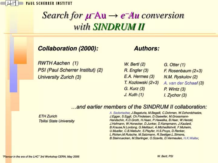
Collaboration (2000): RWTH Aachen (1) PSI (Paul Scherrer Institut) (2) University Zurich (3). Authors: W. Bertl (2) R. Engfer (3) E.A. Hermes (3) T. Kozlowski (2+3) G. Kurz (3) J. Kuth (1). Search for m - Au → e - Au conversion with SINDRUM II. G. Otter (1)

E N D
Collaboration (2000): RWTH Aachen (1) PSI (Paul Scherrer Institut) (2) University Zurich (3) Authors: W. Bertl (2) R. Engfer (3) E.A. Hermes (3) T. Kozlowski (2+3) G. Kurz (3) J. Kuth (1) Search for m-Au→e-Au conversion with SINDRUM II G. Otter (1) F. Rosenbaum (2+3) N.M. Ryskulov (2) A. van der Schaaf (3) P. Wintz (3) I. Zychor (3) …and earlier members of the SINDRUM II collaboration: A. Badertscher, J.Bagaturia, M.Begalli, C.Dohmen, W.Dzhordzhadze, J.Egger, S.Eggli, Ch.Findeisen, D.Gaewiler, M.Grossmann-Handschin, K.D.Groth, H.Haan, P.Hawelka, B.Heer, W.Herold, J.Hofmann, W.Honecker, D.Junker, D.Kampmann, J.Kaulard, B.Krause,N.Lordong, G.Melitauri, A.Mtchedlishvili, F.Muheim, U.Mueller, C.B.Niebuhr, S.Playfer, H.S.Pruys, D.Renker, L.Ricken,M.Rutsche, M.Salzmann, R.Seeliger,L.Simons, B.Steinruecken, M.Starlinger, O.Szavits, D.Vermeulen, H.K.Walter, ETH Zurich Tbilisi State University W. Bertl, PSI
Lepton Family-number Conservation • LFC experimentally well confirmed. BUT: Is there an underlying symmetry? • LFC in Standard Model is a consequence of the assumption mn=0 • mn ≠ 0 leads to LFCviolation (LFV), but decays are suppressed by • most extensions of the SM predict additional sources of LFV • many searches done for LFV processes in decays of m,t,p,K,B,D,W,Z • LFV would be an unambiguous sign of new physics • highest sensitivities reached in m,K and recently t experiments • most popular muon decays: m→eg, m→eee, m-e conversion W. Bertl, PSI
e Nuclear dependence of m→e conversion m R Al Au Pb Ti A m – e conversion in muonic atoms • muonic atoms m-(A,Z) formed in their ground state after stopping m- in matter (O(1ns)) • decay of m-(A,Z) mostly by • “muon decay in orbit (MIO)” • and “nuclear muon capture (MC)” • MIO rate ↓ for Z ↑ ; MC rate ∞Z4 • if m-e conversion - leaving the nucleus in its ground state -exists, it’s boosted by the coherent action of all quarks over the MC process (excited states experimentally not accessible) • m-e conversion results in a two body final state → electrons are monoenergetic m binding energy atomic recoil energy T.S. Kosmas, I.E. Lagaris: J. Phys. G: Nucl. Part. Phys. 28 (2002) 2907 W. Bertl, PSI
m - decay in orbit (MIO) : Radiative Muon Capture (RMC) : Background : a) muon induced Theoretical spectrum : (R. Watanabe et al.: Atom.Data and Nucl. Data Tab. 54 (1993), 165) (Lead spectrum, corrected for shift in gold endpoint energy) Kinematic endpoint ofphoton spectrum only 0.7 MeV below Eme , but strongly suppressed at high energies. Check contribution by investigating positron spectrum ! ( see below ) ) V e • Muon decay-in-flight : M / 1 ( E With pm< 65 MeV/c always below Eme d / N d resolution of 1-2 MeV (FWHM) sufficient prop. (Eme – EMIO)5 W. Bertl, PSI
p E5 PMC SINDRUM Background : b) pion induced Radiative Pion Capture (RPC) : • Kinematic endpoint ofphoton spectrum around 130 MeV ! Branching ratio of order 2%. • Suppression by • fast beam veto (RPC is a strong interaction process) • pulsed beam • keep p/m stop rate in target below 10-9 (chosen in this experiment) Achieved by a combination of degrader (10-6) and decay path (8m →10-3) tune beamline to suppress high momentum tail dz (cm) Probability of p/m with p=52MeV/c to cross a CH2 degrader BUT: distributions broadened by finite beam momentum resolution W. Bertl, PSI
Background: c) electron induced • Electrons in the beam may scatter from the target • Suppression by • beam momentum much below 90 MeV/c • However, • electrons from pion decaysin flight before the degrader • and • from RPC in the degrader • may have higher momenta and represent a serious background source. • Suppression achieved by using their time relation with the proton beam’s rf-structure together with a reduction in phase space (see below) W. Bertl, PSI
Background: d) cosmic induced • Cosmic radiation produce e- which may fake a me event. • Suppression: • Most of them identified by hits not belonging to main track (see below). • g→e+e- pair production in the target : • use passive shielding • veto counter systems • small target mass W. Bertl, PSI
Experimental Set-up Proton beam: 590 MeV, time structure: bursts 0.3 ns wide every 19.75 n pE5-beam line: 52 or 53 MeV/c with ± 2% FWHM (limiting high momentum tail) Transport solenoid PMC: 1.1 T, lead collimator with 60mm hole followed by a 8mm CH2 degrader W. Bertl, PSI
1m A exit beam solenoid F inner drift chamber B gold target G outer drift chamber C vacuum wall H superconducting coil D scintillator hodoscope I helium bath J E Cerenkov hodoscope J magnet yoke I H G F D D E H C A B configuration 2000 • Gold Target (B) (produced by galvanic process to avoid low Z contaminations): • diameter ~ 40 mm • wall thickness 75 mg/cm2 • length 65 cm (no beam focus exists) SINDRUM II SINDRUM II Spectrometer Schematic event display: rf rz PMC tracks left by a 100 MeV e- W. Bertl, PSI
Determine m stops: a) Principle SINDRUM II spectrometer + X-ray detector (Ge) • Muonic X-ray detection from m -Au capture • Method: • using a Germanium diode to monitor yield of 4f5/2→3d3/2 transition (899 keV) or (respectively) • using a large NaI crystal detector to monitor yield of 2p→1s transitions (5765 and 5595 keV) • Well known X-ray -intensities (F.J.Hartmann et al. TU München) and -energies (B.Robert-Tissot et al. Univ. Fribourg) • Calibration: • Acceptance for Ge-diode measured with calibrated sources : 137Cs (662 keV), 60Co (1117,1333 keV) at 3 different z positions Reproduced by simulation within ±3% • Simulation used to determine acceptance for gold transition (899keV) & measured stop distribution AGe = (1.02 ± 0.05stat ± 0.07 sys) 10-6 • Acceptance for NaI (5765,5595 keV) from (simultaneous ) Ge measurement ANaI = (1.01 ± 0.06stat ± 0.08 sys) 10-5 (NaI detector not shown) W. Bertl, PSI
Determine m stops: b) Results Example of a raw m -Au X-ray spectrum taken during a 3 hour run s A m / y a r X-ray / mAs Total m-stops in Au-target: Nm= ( 4.37 ± 0.27stat ± 0.17sys ) x 1013 W. Bertl, PSI
Black: data Red: Monte Carlo Event simulation • m-e conversion, MIO and p-decay-in-flight events simulated with GEANT • Exact description of geometry: • target position • active elements • flanges of vacuum tube • Light propagation & attenuation in scintillator and Čerenkov counters • Discriminator threshold & time resolution of each individual counter (from observed values) • Variation of DC1 anodes & cathodes efficiencies during measurement time taken into account • B-field map used for event reconstruction and simulation • m-stop distribution over target adjusted to measurement W. Bertl, PSI
Trigger condition Circular track trigger Straight track trigger Scintillator hodoscope Driftchamber DC1 Endcap detector Used for main data taking and energy calibration (see below) Cosmic muon trigger used for drift chamber calibration once a day W. Bertl, PSI
Event reconstruction and selection • Trajectory reconstruction: • search for DC1 track elements in drift time patterns of sense wire and cathode strips, independently • sense wire & cath. track elements combined pair wise to maximize number of coincident signals • Drift time conversion to r x f coordinates • → check that track elementspoint to hodoscope hit • pairs of track elements are combined into turns and trajectories are fitted (taking account multiple scattering) Drift time ↔ position relation described by 6 parameters received from “straight track calibration” runs W. Bertl, PSI
Energy calibration & resolution Method: use e+ spectrum from stopped in the target Bme = 1.069 ± 0.001 T (central value) • Requires: • mirror B-field (e+ track instead e- track) • lower B-field (by 52/95) • check B-field linearity (Hall-probe) • change beam line polarity • lower beam momentum (→44 MeV/c) Check resolution (at me settings): Compare radius of helical trajectories between 1. and 2. turn Edge rise over 3mm gives Dpt /pt≈ 1% FWHM Edge position very sensitive to material budget W. Bertl, PSI
Cosmic ray induced background 3 classes of cosmic background events: 1)a track element from a high energetic cosmic muon is present together with a knock-on electron circular trajectory 2)an electron enters the tracking region from outside → track does not origin in the target or has an early signal in one of the fast counters Cuts applied in reconstruction are shown • 3)a “cosmic” photon creates an asymmetric e+e- pair in the target • Minimized by: • shielding from magnet return yoke and lateral lead walls • low target mass • a hole in the yoke on top (for supply lines) excluded in acceptance (loss ~4%) W. Bertl, PSI
Pion induced background • pion stops in target → negligible (beam tuning!) • rad. p capture in degrader + pair prod. • p decay in flight just before degrader e- scattering off the target b) is charge symmetric, c) not e+,e- tracks with p>87MeV/c (signal region excluded) Expected: flat background between 80 and 100 MeV/c (O(10) events) Beam correlated region containing pion induced events (width given by beam momentum spread) W. Bertl, PSI
Final momentum spectra 2 event classes defined based on polar angleQ and rf-phasetrf: • cosQ < 0.4 or |trf -10 ns| > 4.5 ns • cosQ > 0.4 and |trf -10 ns|< 4.5 ns Class 1: No sign for m-e conversion events Class 2: Approximately flat high energy component as expected from pion induced background W. Bertl, PSI
Single event sensitivity Sme i= 1,2 • Nm = ( 4.37 ± 0.32 ) x 1013 total number of muons stopped • Rcapt = 0.9717 ± 0.0002 probability of muon capture in gold • = 0.44 spectrometer acceptance e1= 0.19 efficiency for events of class 1 e1 = 0.014 efficiency for events of class 2 ei : derived from simulation with most parameters adjusted from measurements. Spectrum shape well reproduced. Finally lowered by ~10% to equate numbers of measured and expected MIO events W. Bertl, PSI
Likelihood analysis • 4 contributions to the momentum spectra of class 1 and 2 events considered: • muon decay in orbit (MIO) • m – e conversion • contribution from processes with intermediate photons (like RMC) (taken from observed e+ spectrum) • a flat component (p→endecay-in-flight or cosmic backgrd.) Likelihood distribution Ltot = L1 x L2 (L1 : class 1, L2 : class 2): W. Bertl, PSI
Final Result Likelihood analysis ► zero m-e conversion events are most likely The upper limit at 90% confidence level is given by: (Accepted for publication in European Physical Journal C) Improvement : by 2 orders of magnitude to the previous best limit W. Honecker et al.,(SINDRUM) Phys. Rev. Lett. 76, (1996) 200 and 3 orders of magnitudes to the best pre-SINDRUM limit S. Ahmad et al. (TRIUMF) Phys. Rev. D 38 (1988) 2102. W. Bertl, PSI