Download
1 / 28
300 likes | 546 Vues
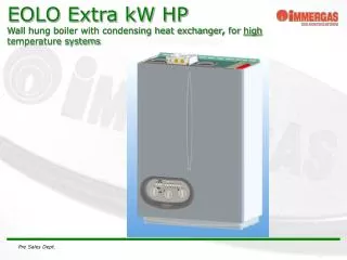
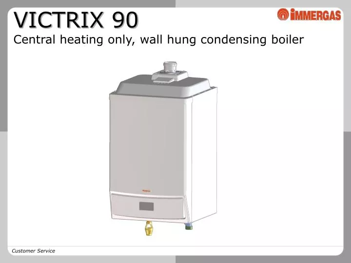
VICTRIX 90 Central heating only, wall hung condensing boiler. Caratteristiche principali. 90 kW output (77400 kcal/h) Outdoor installation ready (IPX5D protection rating) Modulating range from 25% a 100% (22,5-90 kW) Fully pre-mix system (natural gas-G20 e G31-propane)

E N D
VICTRIX 90 Central heating only, wall hung condensing boiler
Caratteristiche principali • 90 kW output (77400 kcal/h) • Outdoor installation ready (IPX5D protection rating) • Modulating range from 25% a 100% (22,5-90 kW) • Fully pre-mix system (natural gas-G20 e G31-propane) • AISI 304L stainless steel condensing module • Electronic board and NTC probes (12 kohm) • 4 bar safety valve • “Green Series” dedicated flue system • Ready for:- Cascade operation (max 8 boilers )- Connection to external cylinder- Connection to Immergas accessories for thermoregulation (external probe, zone managing devices, etc..)
Dimensions and connections • Height = 1086 mm • Length = 600 mm • Depth = 610 mm Key: V – Electric supply G – Gas supply R – System return M – System flow SC = Condensate drain(Ø 13 mm min. internal)
Main components 7 1 2 • Flue hood • Condensing module • Air intake pipe • Fun • Gas valve • Discharge funnel • Sample points (air A) (flue F) • Air vent • Burner • Pump 8 3 9 4 10 5 6
Casing group Ø80 exhaust flue discharge IPX5D cover thermoformed The boiler leaves the factory in B23 type configuration, air is drawn directly from the place where the boiler is installed
Hydraulic circuit Air vent valve Flow NTC probe Return NTC probe Overheating thermostat (Klixson) Circulator 4 bar safety valve M - Flow SC – Condensate discarge G - Gas R - Return
Circulator High head 25-105 Grundfos pump (10 m H2O) Head (m H2O) Head (kPa) Flow rate (l/h) A = Head available to the system on the individual boiler maximum speed. B = Head available to the system on maximum speed with the non-return valve for boilers in cascade (battery)
Condensation module • AISI 304L stainless steel overlapped module • 16 element assembly: flue side 10+6, water side 8+8
Combustion circuit • Flue hood • Condensation chamber • Delivery coils • Siphon • Cylindrical burner • Combustion chamber • Return coils
Combustion circuit Flue hood Condensing module Metalfibre burner Gas manifold Fan Venturi pipe Gas valve Air intake unit
GB-ND 057 Dungs 1:1 pneumatic gas valve 1 - Valve inlet pressure check 2 – Valve outlet pressure check(P3) 3 - Off-set adjusting screw 12 - Outlet gas flow rate adjuster Valve coils are 24 V dc supplied
Control panel Manometer Digital display ON-OFF main switch Adjusting buttons
End user interface It is equipped with a 4 digit display and 6 buttons for programming and adjustment RESET Manual boiler block reset MODE Display menu selection button STEP Parameter selection STORE Data confirmation and memory + Increasing of set value - Decreasing of set value
Printed circuit board • Integrated ignition and modulation microprocessor board • Temperature modulation via two 12 k ohm NTC probes (flow and return) • Parameter adjustment via buttons • Operation status display, temperature and error codes • Output modulation from 25 to 100 %
Printed circuit board • End user adjustments • (free access menu) • Max central heating temperature • Central heating and/or domestic hot water mode operation • Domestic hot water temperature (optional external cylinder) • Qualified technician main adjustments • (code protected menu) • Timer controlled pump post-circulation • Timer controlled central heating • Fan rotations per minute • External probe reading correction
Printed circuit board safeties • Ignition block • Overheating (105ºC) • Fan speed check (fault and revolutions) • NTC probe faults • Low circulation • Low water pressure • Anti-frost protection as low as -5°C • Pump anti-blocking function • Flow overheating (95ºC)
Available connections on the printed circuit board Q-P = External pump G-J = External probe M-O = Thermoregulation device R-H = External cylinder probe F-E = ON-OFF thermostat T-S-K = 3-way valve V-U = Summer switch Y-Z = Analogic input (0-10V)
Thermoregulation options Cascade manager External probe Zone manager Modulating room thermostat
Hydraulic options • Single boiler safety device kit • 3-way valve kit for connection to external cylinder • Hydraulic collector kit for single boiler
Single boiler safety device kit Thermometer Thermometer trap Gas interceptingvalve trap Expansion tankconnection Pressuregauge cock Manual resetthermostat Manual resetpressure switch The devices included in the kit are homologatedby the Italian authority for the job safety (ISPESL)
3-way kit for external tank External storage tank 3-way valve Storage tank probe The probe replaces the one supplied as standard with the boiler An optional kit is available for installation of two external cylinder in parallel
Hydraulic collector kit Includes mud filter on system return pipe
Ø 80 flue system kit Open chamber, fan assisted installation • Horizontal kit: • through-wall discharge • chimney discharge Vertical kit (Max length= 17m) (Max length = 17 m)
Ø80-125 flue system kit Sealed chamber, fan assisted installation Vertical coaxial kit (Max length = 12 m) Horizontal coaxial kit (Max length= 10m)
Ø80 flexible ducting kit Composite material 80mm nominal diameter (89,5 mm externally ) Engineered to be implemented inside chimneys or existing flue exhaust systems Max vertical length: 17 m.
Installation sample Single installation with 200 liter boiler and solar panels ON-OFF room thermostat Solar panel 3-way valve kit for external cylinder
Installation sample Single installation with 3 central heating zones and external tank Zone manager Room managers Modulating thermostat
Installation warnings • Clean the system (pipes, heating elements, etc…) employing specific products • Install a filter on the system in order to recover mud and impurities • Fill the system with correct hardness water (12-15°f) in order to prevent calcium deposits • Employ protective additives in order to prevent corrosion and ensure system efficiency • Connect the safety valve funnel to the drain network system (sewer) • Discharge condensate in compliance with local laws and regulations