Download
1 / 9
90 likes | 188 Vues
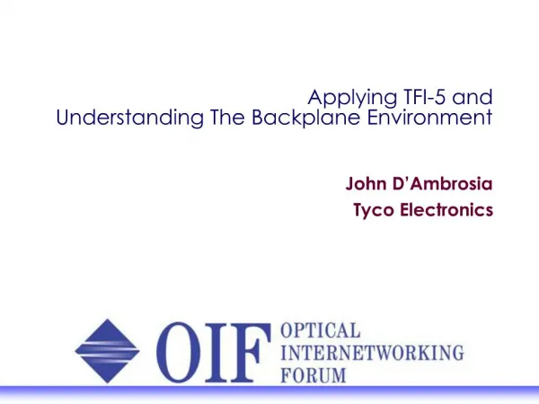
Applying TFI-5 and Understanding The Backplane Environment. John D’Ambrosia Tyco Electronics. Agenda. TFI-5 The Evolution of the Interconnect Variability of the Backplane Environment Example – Transmit De-Emphasis as a Solution The Common Electrical Interface. TFI-5.

E N D
Applying TFI-5 and Understanding The Backplane Environment John D’Ambrosia Tyco Electronics
Agenda • TFI-5 • The Evolution of the Interconnect • Variability of the Backplane Environment • Example – Transmit De-Emphasis as a Solution • The Common Electrical Interface
TFI-5 • Point-to-point connection between a TDM framer and a TDM switch fabric device • 30 inches (76 cm) of total PCB trace including two connector • Support lane bandwidths of 2.488 Gb/s (3.11 Gb/s optional) • Support higher bandwidth across multiple lanes • Example – 4 TFI-5 Lanes OC-192 Traffic • Lane Deskew • Capable of checking for errors • Capable of bit error rate of 10E-12 for PCB
Semiconductors Equalization Board Interface Board Interface Higher Performance Media Higher Performance Media P a s s i v e P a s s i v e Channel Architecture Connectors Pre-emphasis Transmission Media Loss Properties Encoding Techniques Length Construction Alternate Drilling Alternate Drilling Evolution of the Interconnect A c t i v e F r e q u e n c y Active Length
Variability of Backplane Environment 34” System Length, 0.200” Backplane
Next - Common Electrical Interface • 4.976 to 6+ Gigabit and 9.95 to 11+ Gigabit signaling. • Short reach (0 to 200 mm with up to one connector) • Long reach (0 to 1m with up to two connectors) • Example – Backplane Application (0.86m) at 5 Gb/s Tx Output No Equalization Rx Input No Tx Equalization Rx Input With Tx Equalization
Acknowledgements • Slide #4 – D’Ambrosia, Fogg, Laziris-Brunner, and Tailor, “Reliable Serial Data Transmission at 10 Gb/s,” DesignCon 2002. • Slides #5 and #8- D’Ambrosia and Woodruff, “The High-Speed Backplane Initiative – The Technical Challenges It Faces,” DesignCon 2003. • Slides #6 and #7, D’Ambrosia, Dalmia, and Debie, ”The Importance of XAUI Channel Analysis,” Integrated Communications Design July, 2002.