Download
1 / 36
360 likes | 540 Vues
IA32 (AKA Pentium) Instructions. representation/encoding/decoding. How are instructions (opcodes and operands) represented (as numbers)?. General IA32 instruction format. prefixes. Instruction prefixes. Instruction prefixes – 4 groups. Group 1 lock (f0h) repeat (f2h, f3h) Group 2

E N D
IA32 (AKA Pentium) Instructions representation/encoding/decoding
How are instructions (opcodes and operands) represented (as numbers)?
Instruction prefixes – 4 groups • Group 1 • lock (f0h) • repeat (f2h, f3h) • Group 2 • segment override (2eh, 36h, 3eh, 26h, 64h, 65h) • branch hints (2eh, 3eh) • Group 3 • operand-size override prefix (66h) • Group 4 • address-size override prefix (67h)
Ex. Group 3 prefix(operand-size override, 66h) • “The operand-size override prefix allows a program to switch between 16- and 32-bit operand sizes. Either size can be the default; use of the prefix selects the non-default size.” • Ex. Note that both 16- and 32-bit moves below are both B8!
Ex. Using prefix to distinguish between 16- and 32-bit moves. prefix (66h)
How are instructions (opcodes and operands) represented (as numbers)? • 3 different types (plus immediate).
type 2 type 3 imm type 1
00000000 .code ;insert executable instructions below 00000000 main PROC ;program execution begins here 00000000 B8 00000001 mov eax, 1 ;set regs values 00000005 BB 00000002 mov ebx, 2 0000000A B9 00000003 mov ecx, 3 0000000F BA 00000004 mov edx, 4 00000014 BE 00000005 mov esi, 5 00000019 BF 00000006 mov edi, 6
00000000 .code ;insert executable instructions below 00000000 main PROC ;program execution begins here 00000000 B8 00000001 mov eax, 1 ;set regs values 00000005 BB 00000002 mov ebx, 2 0000000A B9 00000003 mov ecx, 3 0000000F BA 00000004 mov edx, 4 00000014 BE 00000005 mov esi, 5 00000019 BF 00000006 mov edi, 6
Using ModR/M and SIB bytes Remaining types
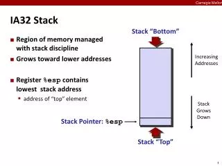
Instruction representation / encoding / decoding ModR/M: Many instructions that refer to an operand in memory have an addressing-form specifier byte (called the ModR/M byte) following the primary opcode. The ModR/M byte contains three fields of information.
Instruction representation / encoding / decoding ModR/M: Many instructions that refer to an operand in memory have an addressing-form specifier byte (called the ModR/M byte) following the primary opcode. The ModR/M byte contains three fields of information: • The Mod field (2 bits) combines with the R/M field (3 bit) to form 25=32 possible values: eight registers and 24 addressing modes. • The Reg/Opcode field (3 bits) specifies either a register number or three more bits of opcode information. • The R/M field (3 bits) can specify a register as an operand or it can be combined with the Mod field to encode an addressing mode.
Instruction representation / encoding / decoding ModR/M: Many instructions that refer to an operand in memory have an addressing-form specifier byte (called the ModR/M byte) following the primary opcode. The ModR/M byte contains three fields of information: • The Mod field (2 bits) combines with the R/M field (3 bit) to form 25=32 possible values: eight registers and 24 addressing modes. • The Reg/Opcode field (3 bits) specifies either a register number or three more bits of opcode information. • The R/M field (3 bits) can specify a register as an operand or it can be combined with the Mod field to encode an addressing mode.
Instruction representation / encoding / decoding ModR/M: Many instructions that refer to an operand in memory have an addressing-form specifier byte (called the ModR/M byte) following the primary opcode. The ModR/M byte contains three fields of information: • The Mod field (2 bits) combines with the R/M field (3 bit) to form 25=32 possible values: eight registers and 24 addressing modes. • The Reg/Opcode field (3 bits) specifies either a register number or three more bits of opcode information. • The R/M field (3 bits) can specify a register as an operand or it can be combined with the Mod field to encode an addressing mode.
Instruction representation / encoding / decoding SIB: (optional) Certain encodings of the ModR/M byte require a second addressing byte (the SIB byte). The base-plus-index and scale-plus-index forms of 32-bit addressing require the SIB byte. The SIB byte includes the following fields: • The Scale field specifies the scale factor. • The Index field specifies the register number of the index register. • The Base field specifies the register number of the base register.
Instruction representation / encoding / decoding Type 2. Opcodes followed by /digit • The Reg/Opcode field contains the digit that provides an extension to the instruction's opcode. A digit between 0 and 7 indicates that the ModR/M byte of the instruction uses only the R/M (register or memory) operand (SIB, Disp, Imm are not used). • (Mod is the addressing mode. For plain register, it is always 11.) X X X X
Instruction representation / encoding /decoding Type 2: Example of opcodes followed by /digit: div ecx
Instruction representation / encoding /decoding Type 2: Example of opcodes followed by /digit: div ecx Step1: From vol 2a, we see that div esi is div r/m32, which is encoded as F7 /6. So the first byte (Opcode) is F7 (indicating div), and the second byte is a ModR/M byte in format /6.
Instruction representation / encoding /decoding Type 2: Example of opcodes followed by /digit: div ecx Step1: From vol 2a, we see that div esi is div r/m32, which is encoded as F7 /6. So the first byte (Opcode) is F7 (indicating div), and the second byte is a ModR/M byte in format /6. Step 2: From table 2-2 (top), • we see that /6 is 110 (or we already knew that), • the two Mod bits for plain old register are 11 (left bottom), • and the three R/M bits for ecx are 001. • So putting all that together in one byte is 11 110 001 (1111 0001) or F1. So div ecx is encoded as two bytes: F7 F1.
Instruction representation / encoding / decoding Type 3.Opcodes followed by /r • /r—Indicates that the ModR/M byte of the instruction contains both a register operand and an R/M operand.
Instruction representation / encoding / decoding Type 3: Example of /r: imul ecx, 12 How is this encoded? Answer: 6B C9 0C
Instruction representation / encoding / decoding Type 3: Example of /r: imul ecx, 12 How is this encoded? Answer: 6B C9 0C
Instruction representation / encoding / decoding Type 3: Example of /r: imul ecx, 12 How is this encoded? Answer: 6B C9 0C
Instruction representation / encoding / decoding Type 3: Example of /r: imul ecx, 12 How is this encoded? Answer: 6B C9 0C C9 = 11 001 001. From table 2-2, we see that: • Mod = 11 (operand in reg (lower left)) • Reg/Opcode = 001 (/r for ecx (top)) • R/M = 001 (specify ecx (lower left)) X X X