Download
1 / 62
670 likes | 1.07k Vues
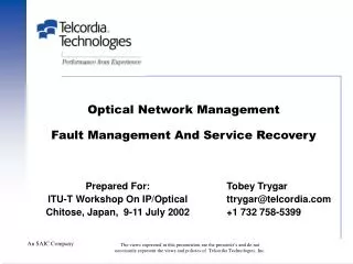
Fault management and WDM network survivability. Lena Wosinska, The Royal Institute of Technology KTH lena@it.kth.se. Outline. Motivation Fault detection and isolation Fault recovery Terminology and concepts Connection availability modeling Protection taxonomy

E N D
Fault managementandWDM network survivability Lena Wosinska, The Royal Institute of Technology KTH lena@it.kth.se
Outline • Motivation • Fault detection and isolation • Fault recovery • Terminology and concepts • Connection availability modeling • Protection taxonomy • Optical layer protection, basics • NP, NE and TE • Connection availability in WDM mesh networks with multiple failures • Introduction • Shared path protection • Our model • Assumptions and connection availability calculation • Evaluation of the algorithm • Conclusions
Motivation (1/2) IP Router ADM S OXC D Single-cable cut: 864 fibers/cable * 160/fiber * OC192/ 1.38 Pbps
Motivation (2/2) • The reliability and fault management aspects of optical high capacity networks are extremely important. • Critical infrastructure • Reliability performance of network elements can not guarantee a sufficient availability of optical channel • Survivability mechanisms in optical layer are required. • Maintaining acceptable level of survivability while reducing network protection costs has become an important challenge for network planners and engineers.
Service classes • Service Availability • Differentiated services • Customer paying more can get better quality of service • “Availability-aware provisioning”
Fault detection and isolation • BER monitoring • Requires access to the bit stream • In transponders and regenerators • Requires known bit pattern or check sums • Optical path trace • An identification of the lightpath • For instance provided by a pilot tone • Alarm management • Forward and backward defect indicators (FDIs and BDIs) • FDI for a section can lead to FDIs for larger sections downstream • Rest of the path
Monitoring methods • Physical layer monitoring using optical time domain reflectometer (OTDR) technology • Optical signal-to-noise ratio (OSNR) using optical spectrum analyzer (OSA) technology • Bit error rate (BER) monitoring using SONET/SDH BER test technology
Fault diagnosis • Hard failures: unexpected events that suddenly interrupt the established channels. • Soft failures: events that progressively degrade the quality of transmission.
Layers within the optical layer OMS OMS OMS OTS OTS OCh-S OCh-S OCh-P • OTS: Optical transmission section • OMS: Optical multiplexing section • OCh-TS: Optical channel transparent section (i.e. all-optical section) • OCh-S: Optical channel section • OCh-P:Optical channel path
Alarm management • Single failure might cause many alarms • Alarm suppression necessary • Forward defect indicator • Backward defect indicator • Defect indicators used for protection switching
Fault recovery: terminology and concepts • Protection, restoration and survivability, • Working and protection paths • Often disjoint paths • Node disjoint or link disjoint • Dedicated and shared protection paths • Revertive and non-revertive schemes • Revertive schemes for shared paths • Protection switching • Path, span and ring switching
Protection vs. restoration (1/2) • Protection • Pre-assigned capacity • Can be very fast • Protection: 1+1 (dedicated), 1:1 and 1:N (shared) • Restoration • Dynamically provisioning of spare resources in the network after failure occurs. • Based on the use of capacity available in the network to replace a failed transport entity. • Network survivability • Network’s ability to continue to provide service in the presence of failures. • Applying protection or restoration. • Usually, networks are designed to survive a single failure
Protection vs. restoration (2/2) Protection Restoration Backup resources are Pre-computed and reserved in advance Backup resources are dynamically discovered upon failure • Advantages • Guaranteed recovery after single failure • Shorter recovery time • Disadvantages • Backup resources “wasted” Disadvantages No guarantee on recovery (backup resources may not be found) Longer recovery time Suitable for layer 3 (IP packet switching) Suitable for lower layers Ring Protection Mesh Protection
Different Fault Recovery Schemes Fault Recovery Schemes Protection Schemes Restoration Schemes Link-based Restoration Path-based Restoration Link-based Protection Path-based Protection Shared Protection Shared Protection Dedicated Protection Dedicated Protection
Protection • Path protection • Find shortest link or node disjoint path pair. • Algorithm: e.g., Bhandari’s algorithm using modified Dijkstra algorithm • Link (span) protection • Find the shortest path bridging working span. • Algorithm: e.g., Dijkstra single source shortest path algorithm. • P-cycle(preconfigured protection-cycle) • A sort of shared span protection • Shortest path as working path. • Find candidate cycles with a hop limit of 10. • Minimum Spare Capacity for 100% restorability. • Mixed Integer Program (MIP) problem formulation. • Make use of optimization tool.
EXAMPLE Link protection Path protection P-cycles Seattle NewYork
Survivable network topologies Standby line Point-to point Mesh Working line S H R
Connection Availability Modeling • Unprotected connection • Available when all the network components used are available • Dedicated-path protected connection • Available when either the primary path or backup path is available • Shared-path protected connection • More complex…
LINK PROTECTION: availability model • UAdd = UC+UT , UDrop = UC+UR • U1 = U2 = …= U n-1 = LUFC + (L/50 - 1)UOFA, • U1p = U2p = …= U (n-1)p = LpUFC + (Lp/50 - 1)UOFA,
PATH PROTECTION: availability model • UAdd = UC + UT , Udrop = UC + UR • UO = (nO-1)LUFC + (nO-2)Unode + (L/50 - 1)(nO-1)UOFA • UR = (nR-1)LUFC + (nR-2)Unode + (L/50 - 1)(nR-1)UOFA
SHR: availability model • UW = nLUFC + nUnode+ n(L/50 - 1)UOFA • UR(SH) = (n-1)UFC + (n-1)(L/50 - 1)UOFA + nUnode UR(NF) = (n-2)UFC + (n-2)(L/50 - 1)UOFA + (n-1)Unode
Mesh recovery: dedicated vs. shared protection 1:1 Protection 1+1 Protection primary primary 2 2 2 3 3 3 backup backup 1 1 1 4 4 4 Shared Protection primary 1 more expensive 6 6 6 5 5 5 share the Backup b/w on link (6,5) 7 A primary 2 less expensive 8 9 B. Mukherjee: Invited Talk at KTH, Sweden Both primary and backup are carrying “live” traffic Backup activated after failure detected…normally, can carry other low-priority preemptable traffic Different categories of recovery… • 1+1 • 1:1 • Shared • 0:1 Not preemptable • 0:1 Preemptable • “X ms” guaranteed recovery time “Multiplexed” protection… more efficient than 1:1
Example: Path Protection B. Mukherjee: Invited Talk at KTH, Sweden 19 1 2,600 1,000 800 1,200 1,900 11 1,300 950 6 2 1,300 15 20 1,400 1,200 900 1,100 1,000 600 700 1,000 1,000 21 16 1,000 12 1,000 1,000 9 3 7 300 800 250 22 900 1,000 4 850 1,000 600 1,000 1,150 850 800 1,100 950 13 1,000 23 17 10 5 650 8 900 800 1,200 900 850 14 18 24 1,200 900 Overall Fiber Distance = 11,300 Km
Path Protection: Failure Recovery B. Mukherjee: Invited Talk at KTH, Sweden 19 1 2,600 1,000 800 1,200 1,900 11 1,300 950 6 2 1,300 15 20 1,400 1,100 1,200 900 1,000 600 700 1,000 21 16 16 1,000 12 12 1,000 1,000 9 9 3 7 7 alarm alarm 300 alarm alarm 800 250 22 900 1,000 4 850 1,000 600 1,000 1,150 850 800 1,100 950 13 1,000 23 17 10 5 650 8 900 800 1,200 900 850 14 18 24 1,200 900 20 ms 20 ms Failure occurrence Failure detection Failure notification
Path Protection Failure Recovery B. Mukherjee: Invited Talk at KTH, Sweden 19 1 2,600 1,000 800 1,200 1,900 11 1,300 950 6 2 1,300 15 20 1,400 1,200 900 1,100 1,000 600 700 1,000 21 16 16 1,000 12 12 1,000 1,000 9 9 3 7 7 alarm alarm 300 alarm alarm 800 250 22 900 1,000 4 850 1,000 600 1,000 1,150 850 800 1,100 950 13 1,000 23 17 10 5 650 8 900 800 1,200 900 850 14 18 24 1,200 900 20 ms 31.5 ms 20 ms 71.5 ms > 50 ms Failure recovery Failure occurrence Failure detection Failure notification
Topology Link Layer (OMS) (terminology used owing to ITU/ANSI) Path Layer (OCh) Protection taxonomy Dedicated Protection (DP) Shared Protection (SP) Dedicated Protection (DP) Shared Protection (SP) Ring OULSR (optical unidirectional line-switched ring) or OMS-DPRing OBLSR (optical bi-directional line switched ring) or OMS-SPRing OUPSR (optical unidirectional path-switched ring) or OCh-DPRing OBPSR (optical bi-directional path switched ring) or OCh-SPRing Point-to-Point 1+1 linear APS (OMS-DP) 1:1/1:N linear APS (OMS-SP) 1+1 linear APS (OCh-DP) 1:1/1:N linear APS (OCh-SP) Mesh No standard term available No standard term available 1+1 OSNCP 1:N mesh protection
Optical layer protection • Advantages • Faster reaction to optical layer failures • More efficient • Disadvantages • Cannot handle client layer failures • Limits to monitoring due to transparency • Smallest protected unit is a wavelength channel (no grooming) • Interworking with higher layers • Protection paths might be substantially longer than working paths
Restoration • Only for mesh topology • Link Restoration • End nodes of the failed link dynamically discover route around link for each connection; link restoration is faster than path restoration • Path Restoration • The source and destination nodes of each connection independently discover back-up route on end-to-end basis; path restoration is slower than link restoration
TE, NE and NP • Traffic Engineering (TE) • Network Engineering (NE) • Network Planning (NP) • “Put the traffic where the bandwidth is” • “Put the bandwidth where the traffic is” • “Put the bandwidth where the traffic is forecasted to be” • TE – online, dynamic, provisioning problem, ms time scale • NE – intermediate problem, months time scale • NP – offline, static dimensioning problem, 5-yr time scale
Example: NP Problem – Path Protection Network Planning • Given: • Network topology • Static traffic demands • Need/Requirements/Constraints: • Set up a primary path and a backup path for each demand • The two paths must be link disjoint (node disjoint too?) • Dedicated or shared backup (based on problem specs) • Guaranteed to recover from a single fiber cut • Goal: minimize cost, e.g., # of wavelength channel
Example: TE Problem – Restoration Traffic Engineering • Given: • Network topology (including # of wavelengths per fiber) • Dynamic traffic demands (or connections) • Need/Requirements/Constraints: • Set up only one path (primary path) for each connection • Try to quickly restore the connection when a fault occurs • Control signaling (GMPLS?) for connection setup + restoration • Note: This method can handle multiple network failures • Three restoration methods: path, sub-path, link
Cross-layer protection • Multiple layers provide survivability • IP • MPLS • SDH/SONET • Each layer acts independently of other layers • Protect paths on all layers, wasteful • Possible contention and unpredictable behavior • Add coordination or separate timescales
Answer the following questions • Which sublayer within the optical layer would be responsible for handling the following functions: • Setting up and taking down lightpaths in the network • Monitoring and changing the optical wrapper overhead in a lightpath • Rerouting all wavelengths (except the optical supervisory channel) from a failed fiber link onto another fiber link • Detecting a fiber cable cut in a WDM line substem • Detecting failure of an individual lightpath • Detecting bit errors in a lightpath
Connection availability in WDM mesh networks with multiple failures
Motivation • Connection availability requirement for critical services is 99.999% or higher • Survivability mechanisms • Dedicated or shared resources? (c.f. trade-off) • Maintaining acceptable level of survivability while reducing network protection costs has become an important challenge for network planners and engineers. • Networks are usually designed to provide 100% survivability for a single failure. • In large networks multiple concurrent failures can not be neglected.
Significance of multiple failures Based on: M. To, P. Neusy, “Unavailability Analysis of Long-Haul Networks”, IEEE JSAC, vol. 12., no. 1, January 1994, pp. 100-109
NSFNet topology Number of nodes: 19 Number of links: 28 Number of connections: 171
Some previous results 5-nines: 99.999% (< 5.26 min/year) cost up to $0.6 M/year 4-nines: 99.99% (< 52.6 min/year) cost up to $6 M/year 3-nines: 99.9% (< 526 min/year) cost up to $60 M/year
Aim To develop a model to calculate connection availability in Shared Path Protection mesh networks with multiple failure assumption
Related Works • A few connection availability models that work with multiple failure assumption in SPP scheme have been proposed. • Limited number of faults (double link failures) or • Limited number of protection paths • Limitations are due to the high computational complexity of these models.
Example 1 Multiple concurrent failures One shared protection path Sharing group Sp= {p1, p2, ..., pn}. Connection twill be available if: 1) pis available; or 2) pis unavailable but bis available, and the failure on phappens before failures to the other primary paths in Sp. Availability of connection t: pi: probability that exact i primary paths are unavailable J. Zhang, K.Zhu, H.Zhang and B.Mukherjee, ICC’2003
Validation p = 1000 km b = 3000 km /10km
Example 2: Matrix based model At most two concurrent link failures can occur One (shared) protection path associated with each working path Balance equations: D.A.A. Mello, D.A.Schupke and H.Waldman, Com.Letters, Sept.2005
Comparison with other models 1 2 3 1 2 3 1: D.Arci, D.Petecchi, G.Maier and M. Tornatore, DRCN’2003 2: J. Zhang, K.Zhu, H.Zhang and B.Mukherjee, ICC’2003 3: M. Jaeger and R.Huerselman, ECOC’2004 Results for Italian network. Scenario 1: working paths of different connections do not traverse common links, fiber failure rate for protection paths were assumed twice the fiber failure rate of working paths (200 FIT/km and 100 FIT/km respectively). Scenario 2: working paths of different connections can traverse common links, fiber failure rate = 200 FIT/km.
Shared Path Protection • Assumptions: • only link failures are considered • a link is either available or failed (two states) • all fiber links fail independently • no wavelength conversion • protection paths can share a wavelength on a common link only if the corresponding working paths are route disjoint
Sharing Conflicts B A D C working lightpath backup lightpath