Download
1 / 95
1.13k likes | 1.89k Vues
Flow Control and Measurement. Creativity without a trip Variations on a drip Giving head loss the slip Chemical doses that don’t dip. Here’s a tip! We can use smart fluids to eliminate software, computers, and electronics!. Fluids Review. What causes drag? Best orientation to reduce drag?.

E N D
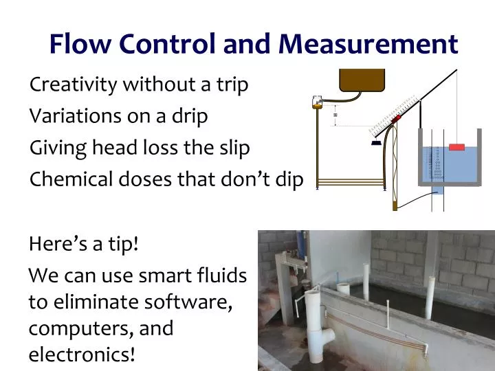
Flow Control and Measurement Creativity without a trip Variations on a drip Giving head loss the slip Chemical doses that don’t dip • Here’s a tip! • We can use smart fluids to eliminate software, computers, and electronics!
Fluids Review • What causes drag? • Best orientation to reduce drag?
Streamlines • Draw the streamlines that begin on the upstream side of the object for these two cases • Which object has the larger wake? • Which object has the lower pressure in the wake? (if streamlines are bending hard at the point of separation, then the streamlines will be close together…)
Why is there drag? • Fluid separates from solid body and forms a recirculation zone • Pressure in the recirculation zone must be low because velocity in the adjacent flowing fluid at the point of separation is high • Pressure in recirculation zone (the wake) is relatively constant because velocities in recirculation zone are low • Pressure behind object is low - DRAG
Fluids Review • Where should the luggage go? • Which equation for head loss? • Which process is inefficient?
Two kinds of drag – Two kinds of head loss Drag (external flows) Head loss (internal flows) Major losses Shear on solid surface Shear on pipe walls Minor losses Separation of streamlines from solid surface Flow expansion • Skin (or shear) friction • Shear on solid surface • Classic example is flat plate • Form (or pressure) drag • Separation of streamlines from solid surface and wake • Flow expansion (behind object)
Overview • Applications of flow control • If you had electricity • Floats • Hypochlorinatorsin Honduras • Constant head devices • Overflow tanks • Marriot bottle • Float valve • Orifices and surface tension • Viscosity • AguaClara Flow Controller • Linear Flow Orifice Meter • AguaClara LinearDose Controller
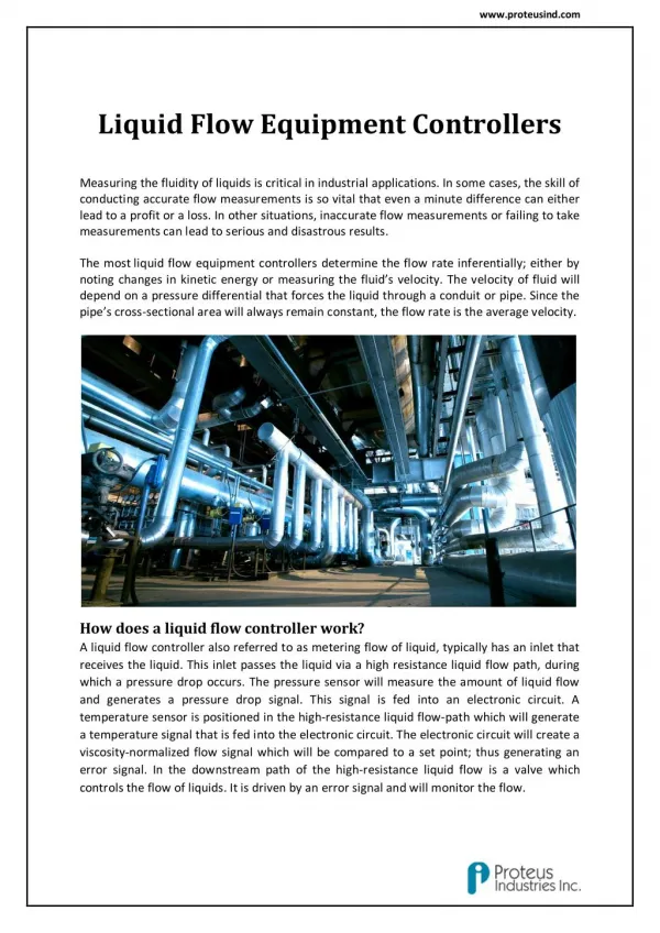
Applications of Constant Flow • POU treatment devices (Point of Use) • clay pot filters • SSF (slow sand filters) • arsenic removal devices • Reagent addition for community treatment processes • Alum or Poly Aluminum Chloride (PACl) ____________ • Calcium or sodium hypochlorite for ____________ • Sodium carbonate for _____________ • A flow control device that maintains a constant dose as the main flow varies coagulation disinfection pH control
Why is constant flow desirable for POU treatment devices? • Slow constant treatment can use a smaller reactor than intermittent treatment • It isn’t reasonable to expect to treat on demand in a household • Flow variations are huge (max/average=_____) • System would be idle most of the time • Use a mini clearwell (tank of treated water) so that a ready supply of treated water is always available 100
If you had electricity… • Metering pumps (positive displacement) • Pistons • Gears • Peristaltic • Diaphragm • Valves with feedback from flow sensors • So an alternative would be to raise the per capita income and provide RELIABLE electrical service to everyone… • But a simpler solution would be better! Consider replacement costs and supply chain
Brainstorm • What are the desired properties of the device that meters chemicals into a water treatment plant?
orifice Supercritical open channel flow! VERY Flexible hose Constant Head: Floats Head can be varied by changing buoyancy of float Unaffected by downstream conditions!
Floating Bowl • Adjust the flow by changing the rocks • Need to make adjustments (INSIDE) the chemical tank • Rocks are submerged in the chemical • Safety issues
Float Orifice Transparent flexible tube Chemical Metering (Hypochlorinator) What is the simplest representation that captures the fluid mechanics of this system? Access door to hypochlorinator tank Overflow tube Chlorine solution Access door to distribution tank PVC valve PVC pipe Chlorine drip Raw water entering distribution tank
This is NOT a minor loss coefficient It is the ratio of the vena contractaarea to the orifice area Hole in a Bucket Vena contracta Orifice Q is flow rate [volume/time]
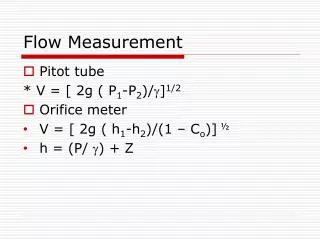
Orifice Equation Torricelli's law Area of the constricted flow Continuity equation Orifice Equation (memorize this!) This equation applies to a horizontal orifice (so that the depth of submergence is constant). For depth of submergence larger than the diameter of the orifice this equation can be applied to vertical orifices. There is a general equation for vertical orifices in the AguaClara fluids functions.
Use Control Volume Equation: Conservation of Mass to find Q(t) volume h0 Orifice in the PVC valve Integrate to get h as f(t)
Finding the chlorine depth as f(t) Separate variables Integrate Solve for height
Finding Q as f(t) Find Aor as function of initial target flow rate Set the valve to get desired dose initially
Surprise… Q and chlorine dose decrease linearly with time! Linear decrease in flow Relationship between Q0 and Atank? Assume flow at Q0 for time (tdesign) would empty reservoir
Reflections • Whendoestheflowrategotozero? • Whatistheaverageflowrateduringthisprocessifthetankisdrainedcompletely? • Howcouldyoumodifythedesigntokeep Q more constant?
Case 2, h0=1 m, htank= 1 m, tdesign=4 days Effect of tank height above valve Case 1, h0=50 m, htank= 1 m, tdesign=4 days htank
Generalizing to Minor Losses • In the previous analysis we evaluated a system with an orifice. An analogous system of slightly more general equations could be developed for any case where minor losses dominate the head loss • An orifice is really a particular case of a minor loss (a flow expansion) • We will compare the minor loss coefficient with the orifice equation vena contractacoefficient to see how they are related.
Comparing Minor loss coefficient and vena contractacoefficient This comparison is for the case of an orifice discharging as a free jet OR into a very low velocity region Average velocity in the orifice Minor loss equation = Orifice equation Don’t confuse these two concepts! Fraction of the kinetic energy that is lost to thermal energy Ratio of the area of the vena contractato the area of the orifice
A related tangent…Design a drain system for a tank Equation from hole in bucket analysis 0 Substitute minor lossand drain for orifice Substitute drain area for orifice area Here Ke is the total minor loss for the drain system
Constant Head: Overflow Tanks Surface tension effects here What controls the flow?
Constant Head: Marriot bottle • A simple constant head device • Why is pressure at the top of the filter independent of water level in the Marriot bottle? • What is the head loss for this filter? • Disadvantage? ___________ batch system
htank hsubmerged dfloat Constant Head: Float Valve Float adjusts opening to maintain relatively constant water level in lower tank (independent of upper tank level) NOT Flow Control! dorifice ? Force balance on float valve?
Flow Control Valve (FCV) • Limits the ____ ___ through the valve to a specified value, in a specified direction • Calculate the sizes of the openings and the corresponding pressures for the flows of interest • Expensive • Work best with large Q and large head loss flow rate
Variable Flow Control Options • Head (or available energy to push fluid through the flow resistance) (voltage drop) • Flow resistance (resistor) • ____________________________________ • ____________________________________ • ____________________________________ • Vary either the head or the flow resistance to vary the flow rate (current) • Vary head by adjusting the constant head tank elevation or the outlet elevation of a flexible tube • Vary resistance by adjusting a valve Orifice i.e. small hole or restriction Porous media Long straight small diameter tube
Float valve with IV drip (Orifice) Variable head or variable resistance? How is flow varied? Variable orifice area How would you figure out the required size of the orifice?
Head Loss: Minor Losses • Head (or energy) loss (hL) due to:outlets, inlets, bends, elbows, valves, pipe size changes • Losses are due to expansions • Losses can be minimized by gradual expansions • Minor Losses are expressed in the formwhere Ke is the loss coefficientand V is some characteristic velocity When V, KE thermal
z x Head Loss due to Sudden Expansion:Conservation of Energy out in At centroid of control surface Where is p measured?___________________________ zin = zout Relate Vin and Vout? Mass Relate pin and pout? Momentum
Head Loss due to Sudden Expansion:Conservation of Momentum Aout Ain x 2 1 Apply in direction of flow Neglect surface shear Pressure is applied over all of section 1. Momentum is transferred over area corresponding to upstream pipe diameter. Vin is velocity upstream.
2 2 2 Head Loss due to Sudden Expansion Energy Mass Momentum Discharge into a reservoir?__________________ Loss coefficient = 1
Minor Loss Coefficient for an Orifice in a pipe e for expansion Minor loss coefficient Expansion losses This is Vout, not Vin Vena contractaarea hl DOrifice DPipe
Equation for the diameter of an orifice in a pipe given a head loss Minor losses dominate, thus he = hl
Driving head for sand column HJR Upflow prevents trapped air Holding container (bucket or glass column) Sealing pipe Pong pipe Sand column (keyword: “prevent”)! Porous media as resistance element What is the purpose of the sand column?
Porous Media Head Loss: Kozeny equation Velocity of fluid above the porous media Kinematic viscosity Dynamic viscosity Analogy to laminar flow in a pipe k = Kozeny constant Approximately 5 for most filtration conditions
Straight Float valve and small tube (Gravity dosing system) ^ chemical stock tank Flow control device If laminar flow! Small diameter tubing hl Neglecting minor losses
Head Loss in a Long STRAIGHT Tube Hagen–Poiseuille • Laminar flow • Turbulent Flow Flow proportional to hf Darcy Weisbach Swamee-Jain f for friction (wall shear) Transition from turbulent to laminar occurs at about 2100
Frictional Losses in Straight Pipes 0.1 0.05 0.04 0.03 0.02 0.015 0.01 0.008 friction factor 0.006 0.004 laminar 0.002 0.001 0.0008 0.0004 0.0002 0.0001 0.00005 0.01 smooth 1E+03 1E+04 1E+05 1E+06 1E+07 1E+08 Re
Hypochorinator Fix http://web.mit.edu/d-lab/honduras.htm What is good? How could you improve this system? What might fail? Safety hazards?
Fs= Fp= Surface Tension Will the droplet drop? Is the force of gravity stronger than surface tension? 2prs
0.080 0.075 Surface tension (N/m) 0.070 0.065 0.060 0.055 0.050 0 20 40 60 80 100 Temperature (C) Surface Tension can prevent flow! Solve for height of water required to form droplet
A constraint for flow control devices: Surface Tension Delineates the boundary between stable and unstable droplets form to right of line Flow control devices need to be designed to operate to the right of the red line!
extra /s) 2.0E-06 2 1.5E-06 1.0E-06 Kinematic Viscosity (m 5.0E-07 0.0E+00 0 20 40 60 80 100 Temperature (C) Kinematic Viscosity of Water This is another good reason to have a building around AguaClara facilities!
extra Kinematic Viscosity of Coagulants
AguaClara Technologies • “Almost linear” Flow Controller • Linear Flow Orifice Meter • Linear Chemical Dose Controller • Orifice/valve based Chemical Dose Controller
AguaClara approach to flow control • Controlled variable head • Float valve creates constant elevation of fluid at inlet to flow control system • Vary change in head by varying elevation of the end of a flexible tube • Head loss element • Long straight small diameter tube • We didn’t realize the necessity of keeping the tube straight until 2012 and thus our early flow controllers had curved dosing tubes