Download
1 / 80
830 likes | 1.22k Vues
Energy Sub-Metering for Measurement and Verification. Objectives. What is measurement and verification? Why implement a measurement and verification program? How do you integrate M&V into the Design Process?. What is Measurement and Verification?. UI M&V Program Based on IPMVP.

E N D
Objectives What is measurement and verification? Why implement a measurement and verification program? How do you integrate M&V into the Design Process?
UI M&V Program Based on IPMVP • What is Measurement and Verification? According to the Efficiency Valuation Organization (EVO), “M&V is the process of using measurement to reliably determine actual savings created with an ECM and/or Energy Program” • EVOwrites and Updates the International Performance Measurement and Verification Protocol (IPMVP).
IPMVP has 4 M&V Options: A,B,C,D A. Retrofit Isolation: Key Parameter Measurement B. Retrofit Isolation: All Parameter Measurement C. Whole Facility D. Calibrated Simulation
Choosing Cost Effective M&V Option Depends on Project A. Retrofit Isolation: Key Parameter Measurement – Utility uses for lighting rebates B. Retrofit Isolation: All Parameter Measurement - Utility uses for HVAC rebates C. Whole Facility – Compare utility bills D. Calibrated Simulation- used for large new buildings and LEED projects
Why do Measurement and Verification? YOU CAN’T CONTROL WHAT YOU DON’T MEASURE
UI M&V Program and Objectives • The purpose of M&V is to document the savings from our Energy Program and/or from specific ECMs. • M&V Plan must balance cost of M&V with project energy savings and required energy information
UI M&V Program and Objectives • M&V is cornerstone for Continuous Cx and maintaining Re-Cxsavings • Actual Energy Usage is compared to Predicted Energy Usage • Issues causing higher energy use are identified and resolved • Repeat Quarterly
UI M&V Program and Objectives • LEED EA 5 M&V - 3 Credits for LEED • M&V and Metering Plan developed in DDs and refined during construction document phase • After Building Occupied: • Compare actual energy usage to modeled energy usage monthly & quarterly • Model is calibrated and building baseline developed • Issues causing higher energy use are identified and resolved early instead of going on for years
Howis Measurement and Verification Implemented? DESIGN PHASE REQUIREMENTS
M&V PLAN Design Dev Phase • Identify what IPMVP Option to be used: New Buildings- Calibrated Simulation • Identify what needs to be measured: Buckets of Energy • Lighting • HVAC • Pumps • Fans • Cooling • Heating • Water • Develop a plan to determine how it will be measured: • Gather Base line data • Decide on meters, trending, calculations, length of time etc. • Screens on the BAS that show the buckets of energy
M&V PLAN - DESIGN Phase • Identify what IPMVP Option to be used: New LEED Buildings- Option D: Calibrated Simulation • Identify what needs to be measured • Develop a plan to determine how it will be measured: • Gather Base line data • Decide on meters, trending, calculations, length of time etc.
M&V PLAN DD Requirements • Choose M&V Option A,B,C, or D • Draft M&V Plan is submitted at DDs for review. • Include meter schematic for each utility, energy type and BAS interconnections to meters • Include trending, calculations, and Cx requirements
M&V PLAN Construction Phase • Cx Agent Verifies that M&V plan is implemented: • Electrical sub-metering is installed and measurements are taking place • Data is collected for reporting. • Reports Reviewed and Acted Upon
M&V PLAN Ongoing • Data is collected for reporting. • Heat Maps, 7 day and monthly usage, energy type roll up and other reports reviewed monthly • Actual usage is compared to modeled usage; model is calibrated and building baseline developed • Issues causing higher energy use are identified and resolved • M&V is cornerstone for Continuous Cxand maintaining Re-Cx savings
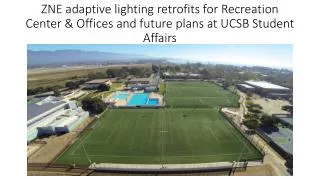
Design Case Study University of Iowa New School of Music Facility
UI School of Music • 186,000 SF, 6 Levels • Performance, Rehearsal, Classroom, Studio, Library and Office Spaces • 63% less energy than 90.1-2007 • Displacement Ventilation, Chilled Beams, Radiant Floor, Standard VAV, Heat Recovery Chillers • LED Lighting, Daylight Harvesting
Sub-metering System Design Process • Define Objectives • Define Building Energy Use Categories • Analyze Building Energy Flow • Determine Meter Placement • Design Data Collection Network
Sub-metering System Design Process • Define Objectives • Define Building Energy Use Categories • Analyze Building Energy Flow • Determine Meter Placement • Design Data Collection Network
Define Objectives • Provide on-going monitoring of energy efficiency strategies • Provide metering to support LEED M&V Plan (Option D - Calibrated Simulation) • Provide detailed performance data for heat recovery chillers • Measure energy used for snow melt • Measure energy used for performance lighting
Design Process • Define Objectives • Define Building Energy Use Categories • Analyze Building Energy Flow • Determine Meter Placement • Design Data Collection Network
Building Energy Use Categories (“Buckets”) • HVAC • Heating • Cooling • Fans & Pumps • Interior Lighting • Domestic Hot Water • Exterior Lighting • Plug/Process • Performance Lighting • Snow Melt • Receptacles & Miscellaneous
Design Process • Define Objectives • Define Building Energy Use Categories • Analyze Building Energy Flow • Determine Meter Placement • Design Data Collection Network
Design Process • Define Objectives • Identify Building Energy Sources • Define Building Energy Use Categories • Identify Building Energy Loads • Analyze Building Energy Flow • Determine Meter Placement • Design Data Collection Network
Building Energy Use Categories (“Buckets”) • HVAC • Heating • Cooling • Fans & Pumps • Interior Lighting • Domestic Hot Water • Exterior Lighting • Plug/Process • Performance Lighting • Snow Melt • Emergency Power • Receptacles & Miscellaneous
Building Energy Use Categories (“Buckets”) • HVAC • Heating • Cooling • Fans & Pumps • Interior Lighting • Domestic Hot Water • Exterior Lighting • Plug/Process • Performance Lighting • Snow Melt • Emergency Power • Receptacles & Miscellaneous
Heat Recovery Chillers [Energy Product] [Hot Water] COP = COP = [Energy Input] [Electricity]