Download
1 / 22
220 likes | 287 Vues
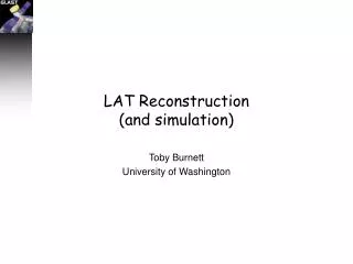
LAT Reconstruction. Toby Burnett University of Washington. Outline. History of GLAST software – back to 1990! GLAST has been driven by software An overview How it works Plans. SAS Organization. Richard Dubois SAS Manager SLAC. Tracy Usher SLAC TKR. Toby Burnett Code Architect.

E N D
LAT Reconstruction Toby Burnett University of Washington
Outline • History of GLAST software – back to 1990! • GLAST has been driven by software • An overview • How it works • Plans GLAST Users Committee Meeting - 23 Oct 03 - T. Burnett - LAT reconstruction
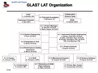
SAS Organization Richard Dubois SAS Manager SLAC Tracy Usher SLAC TKR Toby Burnett Code Architect Mark Strickman NRL CAL R.Schaefer J.Bogart Databases T.Burnett UW Sim/Recon E.dceSilva SLAC Calibrations Heather Kelly GSFC ACD J.Chiang C. Cecchi Obs Simulator Seth Digel Stanford SciTools F. Longo Trieste GEANT4 P Nolan Source ID A.Schlessinger SLAC Release Mgt H.Kelly GSFC Analysis Tools M.Hiruyama Pulsars S.Ritz GSFC Performance Metrics A.Schlessinger SLAC DPF D Band S.Digel Analysis Tools I.Grenier Catalog Analysis D.Band GRB Analysis GLAST Users Committee Meeting - 23 Oct 03 - T. Burnett - LAT reconstruction
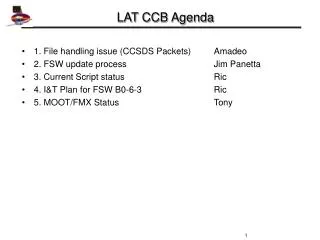
Processing flow, current status Data Pipeline ~80-90% done (Opus) Level 0 Simulation 95% done In use Raw Data Reconstruction 90% done In use Level 1 Prototype database being implemented Science Tools Level 2 GLAST Users Committee Meeting - 23 Oct 03 - T. Burnett - LAT reconstruction
Birth of GLAST code: CERN Canteen #1, summer 1990 GLAST Users Committee Meeting - 23 Oct 03 - T. Burnett - LAT reconstruction
Legacies of that meeting • Object-oriented design for new simulation toolkit • Code is organized into classes • Data hiding in objects • Detector description (geometry, materials, active regions) accessible in same form to both simulation and reconstruction • Interactive application • Combines simulation and reconstruction in one package • Choice of source parameters on the fly • Integrated 3-D display with GUI controls • Interactive control over display of: • geometry: what is where • particles: where they go, what happens to them • detector response: how the active regions respond to deposited ionization (and is it in the right place?) • reconstruction: how well does the pattern recognition and fitting represent the input response? • Easy transition to batch mode, tools to generate n-tuple summaries GLAST Users Committee Meeting - 23 Oct 03 - T. Burnett - LAT reconstruction
The rest is history • 1992: • Bill Atwood and Peter Michelson consider a modern design for the just-launched CGRO/EGRET; Bill starts using the toolkit (called Gismo) to test designs. • Basic attributes of the current design emerge quickly: • Si strip tracker/converter, converters just above strips • Segmented ACD, not in the trigger! • Onboard level 1 trigger, software filter • Segmented CAL. • Large aspect ratio for good FOV, modular design (originally 7x7) • Basic scale (1.8 m square, <10 Rad Len CsI) set by Delta II launch capability • 1994: • Toby Burnett joins, takes over top-level design • Bill and Peter get NASA’s attention with mission concept study • All the basic performance parameters based on GLAST Users Committee Meeting - 23 Oct 03 - T. Burnett - LAT reconstruction
History, cont. • 1995-1998 • Gradual increase in collaboration size, UCSC and SLAC • Start using Kalman filter for track fitting • Steve Ritz joins • Beam tests validate simulation • 1999 • (Dec) AO response submitted following extensive simulations • 2000 • (Feb) LAT selected • Define xml-based geometry data base • Switch simulation toolkit from Gismo to Geant4 • 2001 • Adopt the present infrastructure (all supported elsewhere) • Source management – cvs, repository at SLAC • Package management/ build system – CMT • Execution framework – Gaudi • Component model with Abstract interfaces • Support only linux/gcc and Windows/Developer Studio • Define xml-based geometry data base • Switch from Gismo to Geant4 • 2002 • (Jan) PDR baseline • Choose the name “Gleam” to represent the combined sim/recon executable [GLast Event Analysis Machine] GLAST Users Committee Meeting - 23 Oct 03 - T. Burnett - LAT reconstruction
Currently • Testing new Background model based on AMS Shuttle observations. • Code from onboard filter incorporated into analysis • Preparing for Data Challenge 1. Bottom line: modeling and reconstruction software has driven the development of GLAST, not lagged behind hardware development GLAST Users Committee Meeting - 23 Oct 03 - T. Burnett - LAT reconstruction
A more detailed picture 3 GeV g Source Source Fluxes Fluxes Particle Real Data Transport “Raw” “Raw” Data Data Reconstruction Geometry Description Tail suppressionBackground rejection Geometry Level 1 GLAST Users Committee Meeting - 23 Oct 03 - T. Burnett - LAT reconstruction
Some details: a 1 GeV photon aqua: ACD tilesyellow: Sigreen: W only charged tracks shown no detector response or recon shown GLAST Users Committee Meeting - 23 Oct 03 - T. Burnett - LAT reconstruction
Zoom in to the conversion mind the gap! y x 32.25 mm x y GLAST Users Committee Meeting - 23 Oct 03 - T. Burnett - LAT reconstruction
Angular resolution and track fitting • Intrinsic limits (projected) • multiple scattering: in 1.25% RL (1/2 a “thin” layer): 1.5 mrad * (1 GeV / p) • pitch: 2 mrad for one layer. • [for the astro guys: 1 deg = 17 mrad] • Naïve fitting strategies • Low energy: use only first two layers, since next conversion layer adds error to subsequent layer measurements • High energy: simple least squares fit • Better way: Kalman filter • designed to combine “process” and “measurement” noise. • Equivalent to the naïve limit, but interpolates properly in-between • Implies that there is a measurement of the energy/momentum, at each plane • Even for low energy, follows each track. GLAST Users Committee Meeting - 23 Oct 03 - T. Burnett - LAT reconstruction
Example: 100 MeV gamma GLAST Users Committee Meeting - 23 Oct 03 - T. Burnett - LAT reconstruction
The Calorimeter • 4 layers of 25% RL start shower early, but absorb energy (only 380 MeV in the CsI here • Large gap between modules • Reconstruction is done iteratively with tracker, two passes • Preliminary measurement with basic clustering algorithm, predicts energy and direction • Tracking uses this, and estimates energy in tracker (using observed MS, counting hits) • Calorimeter refines measurement with track direction(s) • High energies: shower shape mind this gap! GLAST Users Committee Meeting - 23 Oct 03 - T. Burnett - LAT reconstruction
The ACD • Extrapolate to plane of each hit tile, measure (signed) distance to edge of the tile • Reject incoming charged particles if inside simulated muon, showing (in yellow) the tile and Si wafers MC track, fit, and projected direction all colinear GLAST Users Committee Meeting - 23 Oct 03 - T. Burnett - LAT reconstruction
Requirements: Onboard: filter factor of ~100. (for downlink) Ground: need another factor of 100 (for science) Simulation: create events that find all the “holes” Ground Strategy Generate useful discrimination variables Apply cuts (or classification trees) Background rejection GLAST Users Committee Meeting - 23 Oct 03 - T. Burnett - LAT reconstruction
Classification • What is it? • A new category of analysis: depends on application of Classification and Regression trees • Common use in “soft” sciences, discovered by Bill Atwood. • A systematic way to find optimal regions in multidimensional parameter space to separate populations: result is expressed as a tree. • Where do we use it? • Determine if energy is well measured (important for track fit) • Choose vertex or single track gamma direction estimate • Assess probability that an event is in the PSF core distribution • Predict the PSF itself • Assess probability that an event is really a gamma ray (vs. background) • How are the trees generated? • With the commercial tool Insightful Miner • Output in the form of XML trees is used by recon software. GLAST Users Committee Meeting - 23 Oct 03 - T. Burnett - LAT reconstruction
Primer from W. Atwood Origin: Social Sciences - 1963 How a CT works is simple: A series of “cuts” parse the data into a “tree” like structure, where final nodes (leaves) are “pure” A "traditional analysis" is just ONE path through such a tree. Tree are much more efficient! Mechanism of tree generation less subject to "investigator basis." Nodes Leaves STATISTICALLY HONEST! GLAST Users Committee Meeting - 23 Oct 03 - T. Burnett - LAT reconstruction
GLAST Users Committee Meeting - 23 Oct 03 - T. Burnett - LAT reconstruction
Data Challenges • Now traditional in HEP experiments • exercise the full analysis chain with simulated data, usually hidden physics • involve the collaboration in science prep early • Doing planning now • Fall 2003 - DC1 • 1 day’s data through full instrument simulation and first look at Science Tools • Focus effort through Analysis Group (S.Ritz) and workshop held in mid-July • Launched at Sept collaboration meeting • Simulation challenge: needs ~500 CPU weeks for background.First use of pipeline • Fall 2004 – DC2 • 1 month’s background/1 year signal • Test more Science Tools; improved Pipeline • Spring 2006 – DC3 • run up to flight – test it all! GLAST Users Committee Meeting - 23 Oct 03 - T. Burnett - LAT reconstruction
Summary • Sim/Recon has played a vital part in the definition of GLAST • With the design now final, the geometry description is approaching a faithful summary • Algorithms for reconstruction and classification continue to be improved • Serious testing, including the pipeline, is about to start with DC1 • Variations on the geometry, but same software is ready to support the current Engineering Module (EM) and Calibration Unit (CU) for 2005 beam test • We are optimistic about the LAT IOCGround Systems CDR, scheduled for 2/2004, with Peer Review in 11/2003 GLAST Users Committee Meeting - 23 Oct 03 - T. Burnett - LAT reconstruction