Download
1 / 21
220 likes | 242 Vues
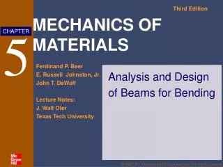
Design of Beams for Flexure. Design of Beams for Flexure. Introduction Moment Curvature Response Sectional Properties Serviceability Requirements (Deflections) Compact, Non-compact and Slender Sections Lateral Torsional Buckling Design of Beams. Beams under Flexure.

E N D
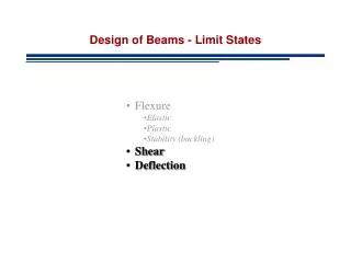
Design of Beams for Flexure • Introduction • Moment Curvature Response • Sectional Properties • Serviceability Requirements (Deflections) • Compact, Non-compact and Slender Sections • Lateral Torsional Buckling • Design of Beams
Beams under Flexure • Members subjected principally to transverse gravity loading • Girders (important floor beams, wide spacing) • Joists (less important beams, closely spaced) • Purlins (roof beams, spanning between trusses) • Stringers (longitudinal bridge beams) • Lintels (short beams above window/door openings)
Design for Flexure • Limit states considered • Yielding • Lateral-Torsional Buckling • Local Buckling • Compact • Non-compact • Slender
Design for Flexure • Commonly Used Sections: • I – shaped members (singly- and doubly-symmetric) • Square and Rectangular or round HSS • Tees and Double Angles • Rounds and Rectangular Bars • Single Angles • Unsymmetrical Shapes
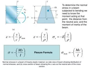
Section Force-Deformation Response & Plastic Moment (MP) • A beam is a structural member that is subjected primarily to transverse loads and negligible axial loads. • The transverse loads cause internal SF and BM in the beams as shown in Fig. 1 SF & BM in a SS Beam
Section Force-Deformation Response & Plastic Moment (MP) • These internal SF & BM cause longitudinal axial stresses and shear stresses in the cross-section as shown in the Fig. 2 • Curvature = = 2/d (Planes remain plane) Longitudinal axial stresses caused by internal BM
Section Force-Deformation Response & Plastic Moment (MP) • Steel material follows a typical stress-strain behavior as shown in Fig 3 below. E = 200 GPa Typical steel stress-strain behavior.
Section Force-Deformation Response & Plastic Moment (MP) • If the steel stress-strain curve is approximated as a bilinear elasto-plastic curve with yield stress equal to y, then the section Moment - Curvature (M-) response for monotonically increasing moment. • In Fig. 4, My is the moment corresponding to first yield and Mp is the plastic moment capacity of the cross-section. • The ratio of Mp to My - the shape factor f for the section. • For a rectangular section, f = 1.5. For a wide-flange section, f≈ 1.1.
Moment-Curvature • Beam curvatureis related to its strain and thus to the applied moment e y (1) (2) (3) (4)
Where Z is the plastic section modulus 1.1 S Moment-Curvature • When the section is within elastic range Where S is the elastic section modulus • When the moment exceeds the yield moment My • Then
Ex. 4.1 – Sectional Properties • Determine the elastic section modulus, S, plastic section modulus, Z, yield moment, My, and the plastic moment MP, of the cross-section shown below. What is the design moment for the beam cross-section. 300 mm 15 mm 400 mm 10 mm 25 mm 400 mm
Ex. 4.1 – Sectional Properties • Ag = 300 x 15 + (400 - 15 - 25) x 10 + 400 x 25 = 18100 mm2 Af1 = 300 x 15 = 4500 mm2 Af2 = 400 x 25 = 10000 mm2 Aw = 10 x (400 - 15 - 25) = 3600 mm2 • distance of elastic centroid from bottom = Ix = 400x253/12 +10000(12.5-145.3)2 + 10x3603/12 +3600(205-145.3)2 + 300x153/12 +4500(392.5-145.3)2 = 503.7x106 mm4 Sx = 503.7x10⁶ / (400-145.3) = 1977.5x103 mm3 My-x = Fy Sx = 680.2 kN-m. Sx - elastic section modulus
Ex. 4.1 – Sectional Properties • distance of plastic centroid from bottom = • y1 = centroid of top half-area about plastic centroid = mm • y2 = centroid of bottom half-area about plas. cent. = mm • Zx = A/2 x (y1 + y2) = 9050 x (256.7 + 11.3) = 2425400 mm3 • Zx - plastic section modulus
Ex. 4.1 – Sectional Properties • Mp-x = Zx Fy = 2425400 x 344/106 = 834.3 kN.m • Design strength according to AISC Spec. F1.1= bMp= 0.9 x 834.3 = 750.9 kN.m • Check = Mp 1.5 My • Therefore, 834.3 kN.m < 1.5 x 680.2 = 1020.3 kN.m - OK!
Flexural Deflection of Beams - Serviceability • The AISC Specification gives little guidance other than a statement, “Serviceability Design Considerations,” that deflections should be checked. Appropriate limits for deflection can be found from the governing building code for the region. • The following values of deflection are typical max. allowable deflections. LL DL+LL • Plastered floor construction L/360 L/240 • Unplastered floor construction L/240 L/180 • Unplastered roof construction L/180 L/120 • DL deflection – normally not considered for steel beams
Local Buckling of Beam Section – Compact and Non-compact • Mp, the plastic moment capacity for the steel shape, is calculated by assuming a plastic stress distribution (+ or - y) over the cross-section. • The development of a plastic stress distribution over the cross-section can be hindered by two different length effects: • Local buckling of the individual plates (flanges and webs) of the cross-section before they develop the compressive yield stress y. • Lateral-torsional buckling of the unsupported length of the beam / member before the cross-section develops the plastic moment Mp. • The analytical equations for local buckling of steel plates with various edge conditions and the results from experimental investigations have been used to develop limiting slenderness ratios for the individual plate elements of the cross-sections.
Local Buckling of Beam Section – Compact and Non-compact Local buckling of flange due to compressive stress (s)
Local Buckling of Beam Section – Compact and Non-compact • Steel sections are classified as compact, non-compact, or slender depending upon the slenderness (l) ratio of the individual plates of the cross-section. • Compact section if all elements of cross-section have p • Non-compact sections if any one element of the cross-section has pr • Slender section if any element of the cross-section has r • It is important to note that: • If p, then the individual plate element can develop and sustain y for large values of e before local buckling occurs. • If pr, then the individual plate element can develop y at some locations but not in the entire cross section before local buckling occurs. • If r, then elastic local buckling of the individual plate element occurs.
Classification of Sections • Classifications of bending elements are based on limits of local buckling • The dimensional ratio l represents • Two limits exist p and r • p represents the upper limit for compact sections • r represents the upper limit for non-compact sections
Local Buckling of Beam Section – Compact and Non-compact • Thus, slender sections cannot develop Mp due to elastic local buckling. Non-compact sections can develop My but not Mp before local buckling occurs. Only compact sections can develop the plastic moment Mp. Stress-strain response of plates subjected to axial compression and local buckling.