Download
1 / 65
650 likes | 656 Vues
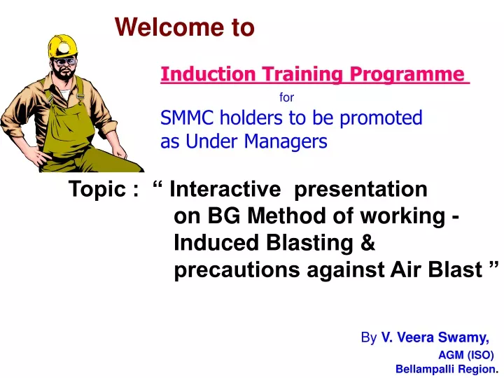
Welcome to. Induction Training Programme for SMMC holders to be promoted as Under Managers. Topic : “ Interactive presentation on BG Method of working - Induced Blasting &

E N D
Welcome to Induction Training Programme for SMMC holders to be promoted as Under Managers Topic : “ Interactive presentation on BG Method of working - Induced Blasting & precautions against Air Blast ” By V. Veera Swamy, AGM (ISO) Bellampalli Region.
INTRODUCTION Coal is the world’s most abundant and safe fossil fuel. World coal reserves are estimated to last almost 200 years from now. The importance of coal as a primary source of energy is significant in India. India has a long history of commercial coal mining covering nearly 220 years from 1774 in the Ranigunj Coalfield.
COAL Demand projections of India XI & XII plan (In Million Tonnes) CAGR – Compounded Annual Growth Rate
The Company wise coal production trend Million Tonnes
Policy decision and initiatives for enhancing coal production in India • EXPEDITING THE PROJECT APPROVAL PROCESS AND FASTER PROJECT COMMISSIONING • For faster execution of projects after they are approved, MoC grants ‘advance action plan’ for larger projects. • PRIVATE MINING • GoI has issued some of the coal blocks to private companies for captive mining. • HIGHER IMPORT • To enable higher imports, the GoI lowered the effective import duty on non-coking coal.
Policy decision and initiatives • OVERSEAS MINING • CIL has formed a subsidiary, Coal Videsh Limited (CVL) to acquire coal blocks in a number of countries including Indonesia, South Africa and Australia. • ENHANCING PRODUCITION FROM OPENCAST MINES • Opencast mines allow higher mechanisation and can therefore ensure faster step-up in production. • INCREASING THE EXTENT OF OUTSOURCING IN VARIOUS MINING OPERATIONS • Outsourcing of mining operations can lead to faster project implementation as the private parties can readily procure machinery.
Policy decision and initiatives • CREATING AN ENABLING POLICY ENVIRONMENT FOR PRIVATE PARTICIPATION • The magnitude of coal shortage is such that active participation of private players is urgently required to broad base the country’s efforts at increasing coal supply.
“ A through review of mining technologies may help in evolving suitable methods for maximizing recovery.”
Strategy of mining in SCCL • Exploitation of coal seams from u/g mines became a major challenge for Indian Coal Mining Industry. • Ever increasing demand year by year as coal is the main fossil fuel used by power sector. • SCCL has initiated several steps like re-organization of existing mines to augment production. • One example is mechanized open cast mining with techno-economic viability.
Strategy of mining in SCCL….Contd • Introduction of mechanization for higher rate of production such as long wall system and intermediate technology etc., liquidation of long standing good quality coal pillars. • About 50 % of coal reserves in India are in seams with thickness more than 4.5 m which fall under the category of thick seams. • Exploitation of thick seams by u/g method poses certain difficulties / problems. • Extraction of thick seams by conventional hand section is neither productive nor viable from conservation point of view. • Percentage of extraction by hand section in thick seams is as low as 25 – 30 %.
Strategy of mining in SCCL….Contd • However, some attempts have been made to extract thick seams with sand stowing. Sand stowing for working thick seams cannot be considered as an option because the cost is prohibitive as sand is becoming increasingly scarce commodity along with timber. • At the same time, coal industry was in search of an economic method for dealing with thick / standing developed pillars. • SCCL is of the opinion that blasting gallery (BG) method is the appropriate method for the extraction of thick seams up to a thickness of 8 – 11 metres. Mining by BG method produces about 1000 T/day with 85 % of extraction which has been in SCCL.
Carbonnage de France (Cdf) suggested Blasting gallery (BG) for extraction of thick seams in India • The 1st BG Panel was started in the country at East Katras colliery in Jharia Coal fields (BCCL) in 1987. • The method was not successful at East Katras colliery where overriding of pillars (strata control) occurred. • In Chora – 10 Pit colliery in Raniganji (ECCL) in the year 1987, the method was partially successful giving encouraging results. • However, it was discontinued due to spontaneous heating. • Expected production and percentage of extraction could not be achieved in both the above mines. • SCCL introduced BG method in collaboration with Carbonnage de France at GDK-10 Incline in the year 1989. for extraction of a coal seam with 11 mtrs. Thickness.
Carbonnage de France (Cdf) suggested Blasting gallery (BG) for extraction of thick seams in India • The method was very successful resulting in 85 % of extraction with high productivity. • At the same mine, where the thick seam was developed fully in top section and partially in bottom section, BG was introduced. • Subsequently, SCCL has introduced BG in other mines also, namely : i. GDK-8, where bottom section was developed by bord and pillar method along the floor of the seam. ii. VK-7 Incline, Kothagudem area, where the seam was developed in two sections. During the development of BG panel, the galleries were driven in staggered manner. iii. GDK – 11 A Inc., RG-I Area and later at No. 21 Area, YD Area in the year 2006.
PRINCIPLE OF BG METHOD • The basic principle of BG method is to extract thick coal seams by drilling and blasting of roof and sides of galleries, which are driven at the bottom of the seam at regular intervals. • Ring holes are drilled in the rooms left between the two adjacent galleries in the roof and sides at regular intervals varying between 0.75 to 1.5 m. by a crawler mounted JUMBO drill. • Blasting is done using explosive cartridges separated by inert spacers and detonating fuse, so that the explosive spreads all along the length of the hole. • Load Haul Dumpers( LHDs) with remote control carry out loading of coal enabling the operator to stand under the supported roof and operate the LHD. LHDs carry the coal from the face and discharge into the armoured chain conveyor, which feeds to the belt conveyor network for transport to the surface. • The development galleries are driven at the floor of the seam. • It is important that the correct size of rise/dip and rooms are maintained to avoid roof control problems during the retreating of the panel.
ADVANTAGES OF BLASTING GALLERY METHOD • Full thickness of the seam can be extracted in a single lift. • Higher percentage of extraction i.e. 75 – 85. • Capital investment is nominal when compared to longwall project. • Easy to train the man power and easy maintenance of the equipment. • Extraction is carried under fully supported roof i.e. with remote controlled LHDs. • Safety of the workmen can be fully ensured. • This method can be also be adopted in virgin/developed seams.
ADVANTAGES OF BLASTING GALLERY METHOD …Contd • Most of the equipment and spares are indigenously available. • Loss of production is minimum while shifting the equipment. • This method is highly flexible as several units are in operation in a district • Even if one of the units is under break down, production from the district will continue to come. • The time required for preparation of panel in relation to the total life of the panel is less than other mechanised methods.
LIMITATIONS OF THE METHOD • This method is not suitable for gassy mines and seams with degree-I gassiness are most preferable. • The method is suitable only for gradient more than 1 in 5 to allow easy movement of tyre mounted LHDs and crawler mounted electro- hydraulic jumbo drills. • Though the percentage of extraction is around 75-85, still coal left in the goaf is likely to create spontaneous heating.
THE MANNER OF EXTRACTION • Each pillar shall be split into two equal parts by level split of width not more than 4.2 m. and height not more than 3m. along bottom section. • The splitting of pillars shall be restricted to one pillar from the pillar under extraction. • The long hole blasting shall not be practiced at any place where two free faces are not provided. • In order to create free faces in this operation / beginning of extraction in BG Method.
THE MANNER OF EXTRACTION…Contd • Before practicing long holes blasting (ring holes) the operation of drilling and blasting are carried out in stages to a height of full thickness to expose roof with increasing angle and length of short holes in bye of the galleries i.e., called “Potato blasting”. • The full thickness of the seam is extracted by blasting a ring of shot holes with about 33 shot holes.
THE MANNER OF EXTRACTION…Contd • The shot holes are drilled in ring pattern and sloping at an angle of about 300 to 400 from the vertical towards the goaf. • The spacing between consecutive rings at shot holes shall be 1.5 m. • The shot holes are drilled in a ring spaced 1.5m. apart by means of JUMBO drill from the level rooms in such a way that they cover half the pillar on rise side and half the pillar on the dip side. • Extraction in level galleries shall be from in bye to out bye forming a diagonal line at an angle of about 600 to the level.
THE MANNER OF EXTRACTION…Contd • A curtain of thickness of coal not less than 1.5m shall be left between two adjacent rooms after blasting of rings. • However, it was observed that this curtain provides protection during remote operation of the LHD in the goaf.
DRILLING • In BG Method, drilling is done by crawler mounted electro-hydraulic jumbo drill which can drill at any angle in the vertical plane, as the method envisages drilling of holes in Fan Pattern. • The length of hole depends on its position and seam thickness. • The jumbo drill can drill upto 30 m. long incline hole with a speed of 1m/minute. • The drill rods are 1.13 m. long with connecting features (both male female type) with rope thread at the end. • The drill rods are provided with a central hole to facilitate wet drilling. Water at the rate of 2.5m3 / hr under pressure of 8-10 bars is flushed during drilling to clean the cuttings out of the hole.
DRILLING • The diameter of drill rod and drill bits are 32mm. and 34 mm respectively. The finished hole diameter is around 43 mm. • On an average, 30- 34 holes are drilled in ring pattern. • All the holes are drilled in the roof leaving towards the goaf line at 550 to 600 from horizontal and 450 towards the goaf from the pillar side. • The holes in the roof are drilled to the seam thickness, whereas the holes in the side are drilled in such a manner that they cover nearly half of the pillar on both dip and rise side from the gallery where jumbo is operating. • A curtain of about 1.5m. in the middle of each pillar is left after drilling for facilitating safe loading by LHD.. However, it was observed that this curtain fell subsequently due to blasting.
Blasting of Ring holes • After drilling is completed, shot holes are charged with the explosive approved by DGMS. • The total number of shot holes in a ring are 33. • The cartridges of explosives are distributed over the whole length of shot holes by spacers tied together by a detonating fuse called RING CORD which are initiated by No: 6 electric detonator. • About 0.5 – 0.6 in length of all holes are stemmed with clay at the end. • On completion of charging and stemming of all holes, the circuit is connected in series. Before blasting, the last installed roof support at the goaf line is removed and next support line is reinforced with extra support.
Blasting of Ring holes …Contd x z PRODUCTION PER RING BLAST The whole ring is blasted in one round using instantaneous electric detonators. Generally, 250 – 350 tonnes of coal is produced in one round of ring blast. (X y - a b)z d r A=width of the gallery=4m B=height of the gallery=2.7m y b a X = length of half pillar=17.5m Y=total working thickness of seam=8.3m Z= distance between successive rings =1.5m D=sp. Gr. Of the coal=1.5 R= percentage of extraction=0.85
Blasting of Ring holes …Contd Specification of Explosives : I-Stage Explosive : Uniring (IEL) • Weight of explosive : 200 g • Diameter of explosive : 32 mm • Length of explosive cartridge : 200 m
Blasting of Ring holes II-Stage b) Explosive Explosive type : Belgex Coal (R), Bharat Explosives Limited Weight of explosive : 185 g Diameter of explosive : 32 mm Length of explosive cartridge : 200 mm Density : 1.18 – 1.19 g/cc VOD : 2826 M/S Air – gap in unconfined condn : 5 cm pass.
Composition of explosive Nitroglycerine : 12 + 0.5% Nitro-Cellulose : 0.2 + 0.5 % Ammonium Nitrate : 46 + 3.0 % Cellulose (Woodmeal) : 1.5 + 0.5 % Salt : 37 + 2.5% Sodium Nitrate : 2 % Others : 6.0 + 0.5 %
Detonating Cord • Type and manufacture : i) Ring chord (IEL) ii) G-Chord (IDL) • Weight of ring cord : 25 g/m • Diameter : 6 mm • Weight of PETN in G-cord : 3.6 g/,
Spacers • Length of long spacer : 600 mm • Length of shorter spacer : 250 mm • Type and manufacturer : Copper coated instant; Premier Explosives Ltd. • Range : 1 • Number : 6 Detonator
POWER RING(IEL) 32 MM DIA, DETONATING FUSE: POWER-CORD(IEL)DIA 4 -4.5 MMPETN-8-9 G/MDETONATORCu COATED INSTANTANEOUS NO. 6 TYPE III Stage :
Blasting of Ring holes II-Stage b) Explosive Explosive type : Belgex Coal (R), Bharat Explosives Limited Weight of explosive : 185 g Diameter of explosive : 32 mm Length of explosive cartridge : 200 mm Density : 1.18 – 1.19 g/cc VOD : 2826 M/S Air – gap in unconfined condn : 5 cm pass.
Composition of explosive Nitroglycerine : 12 + 0.5% Nitro-Cellulose : 0.2 + 0.5 % Ammonium Nitrate : 46 + 3.0 % Cellulose (Woodmeal) : 1.5 + 0.5 % Salt : 37 + 2.5% Sodium Nitrate : 2 % Others : 6.0 + 0.5 %
Detonating Cord • Type and manufacture : i) Ring chord (IEL) ii) G-Chord (IDL) • Weight of ring cord : 25 g/m • Diameter : 6 mm • Weight of PETN in G-cord : 3.6 g/,
Spacers • Length of long spacer : 600 mm • Length of shorter spacer : 250 mm • Type and manufacturer : Copper coated instant; Premier Explosives Ltd. • Range : 1 • Number : 6 Detonator
Support System in BG Method …Contd • The main junction girders are secured tightly by clamps suspended by steel bolts grouted in the roof. • The goaf edges and the entries of the central dip / rise galleries of panel immediately out bye of the goaf edges shall be kept supported by row cogs set an interval of 0.25 m. • All roof bars set on hydraulic props shall be braced suitably. • Adequate setting load of not less 6 T shall be provided.
Support System in BG Method • The level split and dip/rise galleries shall be kept supported by a set of ISMB girders of 150 mm x 150 mm mounted on 40 T hydraulic props at either end. • The first set of cross girders shall be erected close to the goaf edges, but in no case less than 0.7 m. • The distance between two such sets along the gallery shall not exceed 1.00 m/1.5 m depending on the roof conditions. • The roof between the bars shall be suitably lagged by wooden sleepers. • Entire roof is supported for a distance of 40 m. from the face by 250 mm x 250 mm IBMS steel bars placed on 2 No. of 40 T capacity open circuit hydraulic props. • The interval between the bars being 1.00 m / 1.5 m.
Support System in BG Method …Contd • All junctions are supported by 6 Nos of 5.5 m long roof bars which are held in position by means of 2 Nos of 5.5 m roof bars at either end set over a cluster of 4 Nos of hydraulic props at each corner. • In between the roof bars, the roof is further supported by 3 Nos of grouted wooden/bamboo roof bolts. • As a precaution against the dislodging of hydraulic props accidentally by moving machinery, the hydraulic props are tied together to roof bars by means of flexible steel wires.