Download
1 / 29
290 likes | 421 Vues
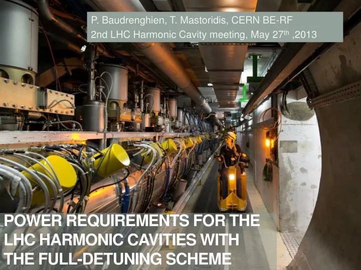
P. Baudrenghien , T. Mastoridis, CERN BE-RF 2nd LHC Harmonic Cavity meeting, May 27 th ,2013. Power requirementS for the LHC harmonic cavities with the full-detuning scheme. Content. Beam-Cavity-TX interaction formula

E N D
P. Baudrenghien, T. Mastoridis, CERN BE-RF 2nd LHC Harmonic Cavity meeting, May 27th ,2013 Power requirementS for the LHC harmonic cavities with the full-detuning scheme
Power Requirements for an Harmonic RF system in LHC Content • Beam-Cavity-TX interaction formula • ACS system with fixed klystron phase and resulting beam phase modulation • Resulting power requirements for the harmonic system • Case study 1: Bunch shortening mode • Case study 2: Bunch lengthening mode • Conclusions
Power Requirements for an Harmonic RF system in LHC BEAM-CAVITY-TX interaction (Joachim’s bible [1])
Power Requirements for an Harmonic RF system in LHC • Equivalent circuit diagram with incident and reflected waves transformed to the cavity gap impedance • Consider a cavity linked to its generator via a circulator, waveguide and coupler • The TX forward current, cavity voltage and beam current are phasors at the RF frequency with a modulation slow compared to an RF period
Power Requirements for an Harmonic RF system in LHC • We can derive a simple relation between Ig, V, Ib and the cavity detuning Dw [1] • The modulation in beam current Ib(t) is imposed by the filling pattern: presence of small gaps for kicker rise time, plus a 3.2 ms minimum gap for the beam dump kicker • So far we have operated the LHC RF for full compensation of the transient beam loading in the ACS cavities: • When proposed in 2007, the power requirement for the harmonic cavities assumed fixed voltage in both ACS and harmonic cavities [2]. After optimization of QL, the required power is then simply proportional to voltage and peak RF component of beam current, formula used in the first proposal
Power Requirements for an Harmonic RF system in LHC THE ACS (fundamental) system and the beam phase modulation
Power Requirements for an Harmonic RF system in LHC Beam phase modulation • Back to the ACS cavities. We now assume that the modulus of the voltage is kept constant but its phase is allowed to vary in response to the transient beam loading • The beam follows the voltage phase modulation. We take the situation in physics: 180 degrees stable phase withib(t) a scalar representing the beam current modulation • The smoother will null the phase modulation of the generator current withig(t) a scalar representing the (hopefully small) required modulation of the generator current phase. Note that we choose the real axis as aligned to the generator current
Power Requirements for an Harmonic RF system in LHC • Now using (2),(3),(4) in the equation (1), we get the beam phase modulation resulting from operating the ACS cavities with a fixed-phase drive with the component of beam current at the fundamental RF frequency, and the optimal (full) detuning • In 1991 Boussard [3] had derived a simplified formula valid in the limiting case sTrev<<1
Power Requirements for an Harmonic RF system in LHC • The following figures consider the HighLumi case: 2808 bunches, 2.2E11 p/bunch, 1.11 A DC, cos2 longitudinal bunch profile, 1 ns base length, bunching factor 0.9, 2 MV/cavity, QL=60000, R/Q =45 W. The cavity is at the optimum detuning (-9039 Hz). We consider the 3.2 ms long abort gap only. Top left: Component ib(t) of beam current at 400 MHz. 3.2 s long abort gap. Top right: Klystron power, almost independent of beam current Bottom left: Phase modulation at 400 MHz.We get 0.180 rad pk-pk (10.3 degrees) at 400 MHz equal to 72 pspk-pk.
Power Requirements for an Harmonic RF system in LHC The harmonic system
Power Requirements for an Harmonic RF system in LHC • We now consider the harmonic cavities at frequency w1= nw • The bunch phase is defined by the Master ACS system (4). The beam current at the frequency of the harmonic cavities is with ib,1(t) a scalar representing the beam current modulation at the harmonic frequency. Given the bunch length and resulting bunching factor, it will be significantly smaller than ib(t) • The harmonic cavity voltage must be locked to the fundamental RF with f1 a constant phase offset between fundamental and harmonic systems. This parameter will be different for Bunch Lengthening and Bunch Shortening modes.
Power Requirements for an Harmonic RF system in LHC • Let us consider the RF-beam phase • For the fundamental we have • For the harmonic system • We have bunch shortening when the two gradients add, i.e. when the two arguments are equal. Bunch lengthening corresponds to opposite gradients, i.e. when the two arguments differ by p
Power Requirements for an Harmonic RF system in LHC Possible buckets in BS mode: the beam current peaks on the zero crossing, negative slope of both fundamental and harmonic RF Possible buckets in BL mode: the beam current peaks on the zero crossing, negative slope of fundamental and positive slope of the harmonicRF Real parts of the fundamental (blue) and harmonic (red) voltages given by equations (2) and (21), plus real parts of the component of beam current at fundamental (yellow) and harmonic (green). Harmonic at twice fundamental frequency (n=2). Left: Bunch shortening mode (1 = -/2) Right: Bunch lengthening mode (1 = /2) Assumes a positive bunching factor at the harmonic frequency.
Power Requirements for an Harmonic RF system in LHC • We now apply Joachim’s formula to the harmonic cavity in order to derive the required generator current • With Ib1(t) following the phase modulation f(t) imposed by the fundamental cavities (4),(5) and V1(t) locked to the fundamental system (6) at optimal detuning Dw0, we get, after some calculations the minus sign in BS mode, the plus sign in BL mode. Dw1 is the detuning of the harmonic cavity, and
Power Requirements for an Harmonic RF system in LHC • We now want to minimize the peak modulus of Ig1(t) over a turn Real-valued term. Independent of beam. This term makes a small excursion, symmetric around zero, in both beam and no-beam segment This term toggles between beam and no-beam segment. In BL mode it will be large (+ sign). In BS mode it can be made small by choosing The cavity tune can be chosen to minimize peak generator current. After some calculations we get
Power Requirements for an Harmonic RF system in LHC • In BS mode, both systems have 180 degree stable phase. The beam phase modulation produces a voltage transient that “helps” the harmonic cavity track the voltage of the fundamental cavity -> required power is reduced • In BL mode, the beam phase modulation with the 0 degree stable phase in the harmonic system produces a voltage slip opposite to the desired RF phase modulation imposed by the ACS system -> much larger power required Left: Beam induced voltage caused by a bunch passage at 180 degree stable phase. Generator driven voltage in blue, bunch induced voltage in red, total voltage in yellow. The bunch causes a positive phase shift (phase advance). Right: Idem with a bunch passage at 0 degree stable phase resulting in a negative phase shift (phase lag). Left: Phase modulation caused by abort gap in a cavity at 180 degree stable phase, with fixed klystron drive. Right: idem with 0 degree stable phase.
Power Requirements for an Harmonic RF system in LHC • In both modes, the detuning must be chosen to minimize the peak generator current The amplitude of the vector is proportional to the klystron current. Beam-on segment in red, beam-off segment in blue. The figure on the right corresponds to the optimal detuning (-15.4 kHz), minimizing the peak klystron current. On the left the detuning (-13 kHz) is almost perfect for the beam segment but will make the klystron power significantly larger in the no-beam segment.
Power Requirements for an Harmonic RF system in LHC Power needed with half-detuning scheme • We now optimize the main coupling to minimize generator peak power • We get Small for high QL • BL mode: plus sign • A good design selects a large Dw01, that is large (R/Q)1and low voltage per cavity • A small loaded QL1 is favorable • The required power will always be larger than with the half detuning scheme • BS mode: minus sign • A good design selects (8) • A large loaded QL1 is favorable (7) • The required power can be much smaller than with half detuning scheme
Power Requirements for an Harmonic RF system in LHC CASE STUDY 1 Bunch shortening mode, 800 MHz cavity
Power Requirements for an Harmonic RF system in LHC • Beam and fundamental cavity parameters: 3.2 ms long abort gap, 1.11 A DC , 1 ns Cosine square line density bunch, 2 MV per ACS cavity (16 MV total) • 2 A RF component of beam current at 400 MHz and 1.44 A at 800 MHz • Assuming 8 MV total at 800 MHz, and 45 W(R/Q)1, the beam phase modulation matches the harmonic cavity perfect for • We get 1.44 MV ideal voltage per harmonic cavity. I consider 1.6 MV/cavity (5 cavities total) • The absolute minimal required power is 55 kW with a QL1,opt=260000. Much reduced from the 300 kW (1/8 V1 Ib,pk1) required without beam phase modulation • Let us use a QL1=100000 instead to make beam loading compensation easier when deviating from the 1 ns bunch length
Power Requirements for an Harmonic RF system in LHC 0.8 ns, 74 kW peak 1 ns, 82 kW peak • In BS mode, phase modulation significantly reduces the needed RF power if the cavity parameters (R/Q and V) are selected properly • The scheme is not very sensitive to bunch length 1.6 MV/cav, QL1=100000 Top left: Generator power with the 1 ns bunch length Top right: Idem with 0.8 ns bunch length Bottom right: Idem with 1.4 ns bunch length 1.4 ns, 130 kW peak
Power Requirements for an Harmonic RF system in LHC CASE STUDY 2 Bunch lengthening mode, 800 MHz cavity
Power Requirements for an Harmonic RF system in LHC • Beam and fundamental cavity parameters as before • To minimize the required power we want to maximize Dw01, that is a large (R/Q)1 and low voltage per cavity (8) • With 90 W(R/Q)1, and 1 MV per cavity (8 cavities total), the absolute minimal required power is 260 kW with QL1=11000 • Alternatively, with 45 W(R/Q)1 we need 330 kW with an optimal QL1=17000 • Without modulation, we would need 190 kW per cavity (1/8 V1 Ib,pk1)
Power Requirements for an Harmonic RF system in LHC 0.8 ns, 296 kW peak 1 ns, 256 kW peak • In BL mode, phase modulation significantly increases the needed RF power • The scheme is not very sensitive to bunch length 1 MV/cav , QL1=11000 Top left: Generator power with the 1 ns bunch length Top right: Idem with 0.8 ns bunch length Bottom right: Idem with 1.4 ns bunch length 1.4 ns, 191 kW peak
Power Requirements for an Harmonic RF system in LHC conclusions
Power Requirements for an Harmonic RF system in LHC • In bunch shortening mode (fundamental and harmonic RF in phase at bunch passage), the phase modulation scheme can much reduce the power requirement on the generators of the harmonic cavities, with a proper choice of the RF parameters: R/Q, QL and voltage per cavity.With this optimal choice a good part of the voltage is induced by the beam passage • In bunch lengthening mode (fundamental and harmonic in phase opposition at bunch passage), the scheme will significantly increase the required RF power, compared to the situation with equispaced bunches, while still keeping it manageable if the voltage per cavity is reduced • The optimal main coupling differs much between the two applications: high QL in bunch shortening mode, where the needed voltage is induced by the beam, and low QL in bunch lengthening mode where the beam induces the wrong voltage change and much power must flow through the main coupler to compensate for that and track the fundamental cavity phase change • In both cases the scheme is not very sensitive to bunch length • Formulas have been derived for the required power and optimal parameters, and can be used to evaluate candidate scenario • Must use more detailed beam current /several gaps)
Power Requirements for an Harmonic RF system in LHC Thank you for your attention
Power Requirements for an Harmonic RF system in LHC References
Power Requirements for an Harmonic RF system in LHC [1] J. Tuckmantel, Cavity-Beam-transmitter Interaction Formula Collection with Derivation, CERN-ATS-Note-2011-002 TECH,Jan 2011 [2] T. Linnecar, E. Shaposhnikova, An RF System for Landau Damping in the LHC, LHC Project Note 394, Feb. 2007 [3] D. Boussard, RF Power Requirements for a High Intensity Proton Collider, CERN SL/91-16 (RFS), US PAC, San Francisco, May 1991