Download
1 / 26
270 likes | 464 Vues
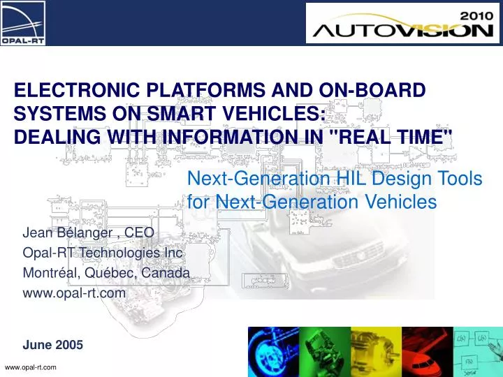
ELECTRONIC PLATFORMS AND ON-BOARD SYSTEMS ON SMART VEHICLES: DEALING WITH INFORMATION IN "REAL TIME". Next-Generation HIL Design Tools for Next-Generation Vehicles. June 2005. Jean Bélanger , CEO Opal-RT Technologies Inc Montréal, Québec, Canada www.opal-rt.com. Opal-RT in Brief.

E N D
ELECTRONIC PLATFORMS AND ON-BOARD SYSTEMS ON SMART VEHICLES: DEALING WITH INFORMATION IN "REAL TIME" Next-Generation HIL Design Tools for Next-Generation Vehicles June 2005 Jean Bélanger , CEO Opal-RT Technologies Inc Montréal, Québec, Canada www.opal-rt.com
Opal-RT in Brief • Established in 1997 • RT-LAB: Real-Time Simulation Platform for Simulink™ and SystemBuild™ • Hardware in the Loop for Demanding Simulations • Distributed, Parallel Processing using Off-the-Shelf Technologies – PC, FireWire, QNX, NI, FPGA etc • Scalable Power for the most complex dynamic models • Comprehensive API for on-line tools for visualization and interaction, eg LabVIEW™ • 50 Employees • Over 200 Customers Worldwide…
Core Markets & Main Customers Automotive • GM, Ford, Toyota, Hyundai, Peugeot, Audi/VW • Tier 1: Delphi Delco, Bosch, Visteon, Allison Transmission Electrical & Power Electronic Systems • GE, ABB, Hydro-Quebec, Mitsubishi Electric etc Academic Research and Education • US: MIT, Berkeley, Michigan, Ohio State, Texas (UT and A&M) etc etc. • Canada: Windsor, Waterloo, Alberta, UQ (AM, TR, AC), Ecole Polytechnique, ETS, McGill etc etc.
Outline • Technology Convergence in the Automotive Industry • Modularization of Electro/Hydraulic/Mechanical Systems • The Challenges arising from increased in-vehicle electronics • Simulation, Testing and Validation Process and the Tool Chain to support it • Challenges and Opportunities for the Canadian Automotive Industry
Technology and Market Convergence “Electronics represent more than 20% of an average vehicle's value. Since the majority of new automotive technologies being developed are electronic, this percentage is projected to double by the year 2010.” Delphi Electronics, 2003
Technology and Market Convergence “The global automotive semiconductor market will grow from a value of $12.3 billion in 2002, to just over $17 billion by 2007. The largest target application for automotive silicon is body and chassis control, which includes electronic traction, suspension and stability control systems. This segment commands approximately 26% of the automotive semiconductor market and will be worth $4.4 billion in 2007.” ABI Research, 2002
Technology and Market Convergence 50% = $8.5bn 2007 Total: $17 billion 2002 Total: $12.3 billion
Automotive System Modularization • Engine Control • Transmission Control • Active Suspension • Active Camber • Traction Control • Stability Control • Power Steering • ABS • “X-by-Wire” • Electric Drives • Energy Generation • Energy Storage SystemModularization drives the need for standard dynamic components and control systems across vehicle platforms. Software determines system behavior and how the components interact with each other Motorola (paraphrased from AEI Magazine)
More Electronics = More Software! Power Steering Error CONTROLLER.exe has caused a fatal error. If the problem continues, please contact your vendor. Press Ctrl, Alt, Del to restart
Challenges • System complexity will dramatically increase with • The number of interconnected controllers • software functionality • Number of engineering teams • Complexity will increase even more with the introduction of fuel-cell and hybrid-electric vehicles • Safety margin will decrease • The total cost of failure will increase dramatically • User tolerance to failure will decrease • System will need to be designed for testability How do we develop testing strategies to assess the reliability and safety of complex electro/mechanical/hydraulic systems while maintaining, or even reducing, costs? “Our ability to design complex systems currently exceeds our ability to test these systems…” Opal-RT Customer, GM
Solutions “Virtual” Prototyping through simulation will play an increasingly key role in system design, commissioning and test. • Automotive and electrical system manufacturers will increase the use of simulation • to reduce time-to-market and R&D cost • and to increase end-user functionality, quality, safety and reliability Connection to real components through Hardware-in-the-Loop (HIL) Testing is critical to this strategy • Validation of controller before integrating into the prototype vehicle reduces errors and costs • Validation of model against the real thing improves the whole process, dramatically reducing development cycles and time-to-market This process is now well defined and widely adopted…
THE ‘V’ DEVELOPMENT PROCESS Highly iterative process Design Structural (CAD) Dynamics Maintenance Plant commissioning Deploy (Production) Validate FEA Off-line Simulation Test track in-vehiclecalibration(commissioning) Virtual Prototype HIL, Real-Time Simulation Visualization Lab TestingTest cells With actual controller Design and Development Control Prototype Physical Components RT Simulation + HIL Validation and Integration Implementation Production CodePrototype Component
THE ‘V’ DEVELOPMENT PROCESS Complete Vehicle Power Steering Braking Transmission Engine Multiple Concurrent Development Teams
Control System Design Tool Chain Production & Quality Control Design Specification & Requirements Definition Hardware in the Loop Plant Simulation “Virtual Prototype” Controller Integration, Tuning, Calibration Controller Prototyping Controller Unit (ECU)Test HILBOX: Production Code RT-LAB MULTI-ECU SIMULATION CLUSTER ECU Memory Interface RT-LAB Simulation Server mSTACK In-vehicle processor RT-LAB Engineering Simulator Design & Development Validation & Integration RT-LAB Rapid Prototyping Controllers PC/104 3rd-Party I/O FPGA I/O Signal Conditioning Specialized Interfaces (CAN, Flexwire, MOST etc) RT-LAB TestDrive Hand-Coding or Automatic Code Generation…
RT-LAB™ Engineering Simulators Vehicle Dynamics Body Electronics Transmission Engine Hardware in the Loop From subsystem simulation… Each engineer with his/her own simulator
RT-LAB™ Engineering Simulators Vehicle Dynamics Body Electronics Transmission Engine Hardware in the Loop …to virtual system integration Subsystem simulations come together into one simulator
Challenge for Canada • Strategists must not lose sight of the growing trend towards the use of in-vehicle electronics, particularly for vehicle control – a $8.5bn US market by 2007 • It will be critical to develop an automotive industry strategy that includes the ability to design and test advanced embedded car electronics for this market • If Canada doesn’t act now, emerging countries like India and China will soon compete through their low-cost, highly educated workforce, and rapidly developing R&D capability Can we afford to be left out of this market?
Recommendation Increase our expertise in all aspects of automotive software development, testing and implementation by 1) collaborating with major OEMs and Tier 1 suppliers on new product development and testing 2) attracting major OEMs and Tier 1 suppliers to carry out some of their R&D in world-class Canadian facilities 3) developing our own expertise through special projects, funded by Canadian partners, independently of OEMs, if necessary For Example…
Example: Virtual Vehicle Test Cell Facility Facility allows manufacturers to “road-test” new or modified vehicle components without a specialized test vehicle. Dramatically reduces costs (at least $500k per test vehicle eliminated) Automated, repeatable tests Climatic extremes without driving to the Arctic or Arizona The World’s First Virtual Vehicle Test Cell opened in September 2002 at SwRI, San Antonio, Texas It is now fully booked for the next three years and work has begun on a second facility Other automotive research organizations are now planning their own facilities around our technologies Photos courtesy Southwest Research Institute
Virtual components Driver/Road Course RoadLoad(Test Track) Driveline(Tires, suspension, driveshaft) Trans-mission Engine ECU Real components Virtual Vehicle Test Cell Facility: How it Works Using a Model-based approach means that component models that were developed at the design stage by different groups or suppliers can now be incorporated into an RT-LAB Engineering Simulator in the Test Cell Photos courtesy Southwest Research Institute
Virtual components Driver/Road Course RoadLoad(Test Track) Driveline(Tires, suspension, driveshaft) Trans-mission Engine ECU Dyna-mometer Transmission ElectricMotor Real components Virtual Vehicle Test Cell Facility: How it Works As the test component becomes available from the manufacturer, it can be readily connected to the simulator via low-inertia dynamometers, bypassing the virtual component. This provides extremely high-fidelity simulation of the engine and test-track loads on the component, and allows the test program to commence with minimal delay Photos courtesy Southwest Research Institute
Virtual components Driver/Road Course RoadLoad(Test Track) Driveline(Tires, suspension, driveshaft) Trans-mission Engine ECU Dyna-mometer Transmission ElectricMotor Real components Virtual Vehicle Test Cell Facility: How it Works As the test component becomes available from the manufacturer, it can be readily connected to the simulator via low-inertia dynamometers, bypassing the virtual component. This provides extremely high-fidelity simulation of the engine and test-track loads on the component, and allows the test program to commence with minimal delay Photos courtesy Southwest Research Institute
Summary • Vehicular electronics is a rapidly growing market, particularly in Body & Chassis, and Powertrain Control • Demand for active electro/mechanical/hydraulic systems will drive the demand for more research into control development and integration • An $8.5bn market cannot be ignored and we need to plan for success in this market now • As an industrial region with all the right skills, Canada is well placed to become a leader in research in this area
Final Message • Professional-grade tools for ECU development and testing are already available and are being used by the major automotive players • Canada has a ready supplier of the right tools to facilitate the development process and help build the required R&D facilities to service this market Don’t build the hammer, build the house! Thank you


![Toward The Next [ Next [ Next … ] ] Generation of Meta-Modeling Tools](https://cdn3.slideserve.com/5854127/toward-the-next-next-next-generation-of-meta-modeling-tools-dt.jpg)