Download
1 / 15
190 likes | 402 Vues
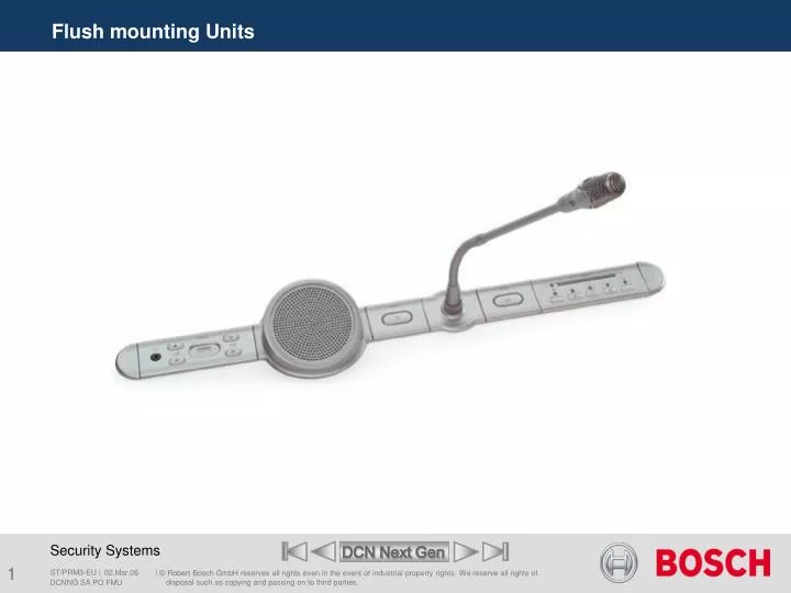
Flush mounting Units. 5. 1. 2. 3. 4. 32-Channel Language Selector . 1 Headphones output 3.5 mm jack socket to connect headphones.

E N D
Flush mounting Units DCNNG SA PO FMU
5 1 2 3 4 32-Channel Language Selector • 1Headphones output 3.5 mm jack socket to connect headphones. • 2Volume control Two keys to control the volume of the headphones.The volume level is adjustable between -60 dB and 0 dB (60 steps). It is also possible to mute the volume. The default volume is -21 dB. • 3Display Numeric display for channel number indication. • 4Channel control Two keys (up, down) for channel selection. • 5External A 3-pin header to connect an extra headphones socket. Headphones connector I&U Instructions DCNNG SA PO FMU
6 9 7 8 32-Channel Language Selector • 6DCN cable A2 m long cable with a male connector. • 7DCN Socket A female socket for loop-through. • 8Solder spots Three solder spots to configure the channel selector. • Enable/disable auto increment/decrement volume. • Enable/disable auto restore function. • Volume and channel settings. • 9Reduce output A 2-pin header connector to reduce the headphone output level of the channel selector by an additional 18dB when the delegate unit microphone- LED is on. I&U Instructions DCNNG SA PO FMU
Voting Unit Range DCNNG SA PO FMU
1 3 1 3 2 2 Voting Unit to connect to the Trunk Cable • 1Condition LED • 2Voting buttons Each voting button has a yellow LED. The LED shows the condition of the voting button. • 3External contact plug external contact on behalf of(Fraud push_ button) or (Finger print reader) operation. I&U Instructions DCNNG SA PO FMU
4 5 6 Voting Unit to connect to the Trunk Cable • 4 De-init switch Erases the address of the delegate unit. All LEDs on the delegate unit come on when it does not have an address. • 5DCN cable 1 meter DCN cable with male connector • 6DCN cable 1 meter DCN cable with female connector I&U Instructions DCNNG SA PO FMU
Installation materials for flush mounting • Couple Pieces (Set of 50 Pieces) • End Caps (Set of 50 Pieces) DCNNG SA PO FMU
Dual Delegate Interface (DDI) I&U Instructions DCNNG SA PO FMU
Dual Delegate Interface (DDI) 1 • 1DCN cable 2 m cable with a male connector. • 2Mode selector 7 8 2 3 4 • 3RJ11 socket to connect: • An Intercom Handset • An channel selector to reduce the channel selector headphone output level with 18 dB when the delegate microphone-LED is on. • 4RJ11Voting/Control inputs to connect: • Microphone Control Panels • An Microphone Priority Panel • Voting Panels to the dual delegate interface I&U Instructions DCNNG SA PO FMU
6 7 8 Dual Delegate Interface (DDI) • 6 DCN Socket A female socket for loop-through • 7Audio outputs To connect the loudspeakers • 8 Audio inputs To connect external audio sources such as: • Delegate Microphone • Mixer outputs at audio line-level I&U Instructions DCNNG SA PO FMU
9 10 11 12 13 Dual Delegate Interface (DDI) • 9De-init switch • Erases the address of the dual delegate interface. The red LED adjacent to the de-init switch comes on when the dual delegate interface does not have an address. • 10Input adjustment potentiometer • Adjusts the sensitivity of the audio input. • 11Input type switch • Sets the type of audio input. Remove the lid of the dual delegate interface to get access to the controls inside. • 12Input adjustment switch • Sets the sensitivity of the audio input. • 13Signal level switch • Sets the signal level of the audio input. I&U Instructions DCNNG SA PO FMU
Voting Unit to connect to the Dual Delegate Interface (DDI) • 1Condition LED 1 2 5 3 4 • 2Card reader can give access to the voting panel. • 3Voting buttons Each voting button has a yellow LED. The LED shows the condition of the voting button. • 4External contact plug external contact on behalf of(Fraud push_ button) or (Finger print reader) operation. • 5Solder spot Configures the external contact plug. I&U Instructions DCNNG SA PO FMU
Dual Delegate Interface configurations Two delegate positions with full functionality Chairman position with full functionality I&U Instructions DCNNG SA PO FMU
Quick Reference Card Quick Reference DCNNG SA PO FMU
Flush Mounting Units End of section SA PO Menu DCNNG SA PO FMU