Download
1 / 18
180 likes | 187 Vues
IBL Data and TTC Transmission Baseline. Presented by David Nelson djn@slac.stanford.edu. Contributors. ATLAS Pixel System Design Task Force for SLHC Upgrade A. Grillo – lead F. Anghinolfi, M.B. Barbero, R. Beccherle, G. Darbo, F. Philippe, D. Ferrere, M. Garcia-Sciveres,

E N D
IBL Data and TTC Transmission Baseline Presented by David Nelson djn@slac.stanford.edu
Contributors • ATLAS Pixel System Design Task Force for SLHC Upgrade • A. Grillo – lead • F. Anghinolfi, M.B. Barbero, • R. Beccherle, G. Darbo, F. Philippe, • D. Ferrere, M. Garcia-Sciveres, • T. B. Huffman, S. Kersten, S. Malyukov, • D. J. Nelson, F. Hügging. • Transmission testing • Martin Kocian, D. J. Nelson, Su Dong
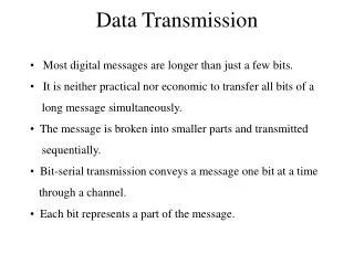
IBL I/O system proposed by task force. • Due to the short schedule for development and to minimize risk and cost. • Note that the IBL is not a stand-alone system, but an add-on. • Use as much of the existing elements as possible while meeting requirements. • Minimize development effort, cost and integration time with existing system • The LHC down time will be close to normal with minimal commissioning time for the IBL. • Man-power is in short supply for development work • New elements would be difficult to qualify given the schedule. • Perform early testing of components. • For example, the opto-board to electrical EOS communication can be proto-typed immediately as proposed by the task force.
IBL I/O system Requirements & Recommendations. • Data Rates • The B-Layer at 3.7 cm and a luminosity of 3 x LHC indicate that a data rate of 86 Mbps per FE-I4. Allow for 30% uncertainly in occupancy simulation. There is also likely need for 8B-10B encoding for clock recovery which adds 20% overhead. The total data rate could be 129 Mbps with the uncertainty and 8B-10B encoding. • An alternate approach is to scale existing layers L1 & L2 maximum bandwidth to 3.7 cm radius. • Both approaches lead to a data rate set to 160M bps • Task force recommendation • The data rate per FE-I4 is set at 160Mbps
IBL I/O system Requirements & Recommendations. • Clock & Command • Two options were considered. • Send 40MHz and provide a clock multiplier on the FE-I4 • This allows the TTC chain to operate as now but requires a new clock multiplier on the front-end readout chip. • FE-I4 designers are OK with developing a clock multiplier. • Send 80MHz and use both edges as now done to achieve the 160Mbps data output. • Require modifications to the BOC & possibly to the ROD to produce higher speed TTC • A synchronization protocol would have to be developed and built into the FE-I4 to provide correct phasing of the beam crossing to the 80MHz clock. • Require a new DORIC chip to decode the clock at twice the frequency. • Task force recommendation • Take the decoded clock (40MHz) & commands (40Mbps) from the DORIC and propagate them as separate LVDS lines from the opto-boards to the FE-I4s. It should be possible to connect two FE-I4 chips to each clock and command thus reducing the electrical links by a factor of two.
IBL I/O system Requirements & Recommendations. • Task force Data Output Links recommendations: • Run links at 160Mbps • One link between each FE-I4 and the opto-boards where the VDC and VCSEL will convert them to optical. One optical link per LVDS link. • LVDS over copper twisted pair, 36 AWG • Include 8B-10B encoding in the FE-I4 • The BOC would include 8B-10B decoding as well
IBL I/O system Requirements & Recommendations. • BOC/ROD • BOC will need to be redesigned to handle receipt of the 160MHz data stream and decode 8B-10B data back to its raw form • The simplest adaptation would be to have the BOC hand off the data to the ROD as four 40 Mbps data streams for each input link as it now separates the 80 Mbps data streams into two 40 Mbps streams. • This will minimize changes in the ROD and still require one S-Link per two 40 Mbps data streams. • The BOC could hopefully be backward compatable. • Strong requirement is that the RODs built for the IBL be backward compatible with the existing ROD so they can be used for spares.
IBL I/O system Requirements & Recommendations. • Possible Opto-board Upgrade • Some redundancy could be added to allow dead TTC and Data Out links to be replaced by spare channels. • A separate control of the VCSEL optical power would improve robustness. • Task force recommendations • These added features would be helpful for the existing system and should be seriously considered for the SLHC upgrade. • The IBL is a small portion of the system and is short lived. • Therefore The task force recommends not to include these upgrades to the opto-boards • DCS and Interlocks • Task force recommendations • Use the same components that are used in the present Pixel system
Near Term Tests, (Task Force Recommendations) • Several aspects of the proposed plan for the IBL should be tested in the very near future. • Reliable electrical transmission of DC balanced 160 Mbps signals over the estimated 4 meters from the FE-I4 chips to the planned location of the opto-boards should be verified. • Slide 15 illustrates successful tests • Test the ability of the existing VDC chip to drive 160 Mbps. • Verify that the present DORIC chip can reliably transmit 40 MHz clock and 40 Mbps commands over 4 meters via twisted pair copper. • Verify that two FE-I4 can share the same clock and command lines. • A test of these services chain using existing opto-board and LVDS test chip should be employed as soon as possible. Results of these tests could impact these architectural decisions. • Slide 15 illustrates that the ATPIX test chips performs well
Options for FE-I4 Design • The FE-I4 should include a reset-clock-multiplier command. • The FE-I4 should be provided with a second 80 MHz input. • This would allow to either use the clock multiplier or this alternate input. • Pre-emphasis could be added to the FE-I4 if tests show difficulty in transmitting 160 Mbps • Pre-emphasis could be added to the DORIC if tests show that the present DORIC has trouble transmitting data over 4 meters. • Could this be a commercial chip which would avoid a design effort.
IBL EOS Services • Power • The current system uses an equivalent of 4 pair of 17 AWG Al wire. • Total current for 16 FE-I4 chips is 9.6 Amps * 2 is 19.2 amps for total pin current. • Four meters length • The cross section of the 4 pair is 8.3mm^2. • A number of power connections have been discussed • Use Hirose DF30, 40 pin board to board connectors • Plastic body is Liquid Crystal Polymer, (LCP) Radiation good to > 100MGy • Contact rating is 0.3 amps • De-rate to 0.15 amps • 19.2 amps / 0.15 = 128 pins • Would need 3 each 40 pin connectors • Wire gauge would need to be 28 AWG Al or larger • Can the wires be silver plated for solderability? • Directly solder wires to IBL • Could use any combination of wire gauges to attain required voltage drops. • No contact de-rating needed. • More reliable • More difficult to handle during fabrication.
IBL EOS Services • Clock and Command • 16 pair of 36 AWG copper twisted pair • 8 clock, 8 Command. • One pair for two FE-I4s • One 40 pin HRS DF30 connector • Could directly solder wire to IBL • Data link • 16 pair of 36 AWG copper twisted pair • One pair per FE-I4 • One 40 pin HRS DF30 connector • Could directly solder wire to IBL • High Voltage • Two 20 pin HRS DF30 connector • 8 HV circuits? • Use low voltage returns • Could directly solder wire to IBL • This would accommodate the voltage compliance • DCS • Separate connector
IBL EOS Services • IBL – 84 cm • EOS Shrink & surgical Tubing • EOS with HRS Connectors & 0-80 Screws – 10 cm • Still playing with fastening mechanism
IBL EOS Services with traveling harness • EOS with traveling with traveling harness • All wires soldered and spooled • Assembly test with multi-stave 10 cm -15 cm diameter spool Direct solder wires IBL
IBL Data Transmission using the ATPIX Transceiver Chip • Test-up includes: • Xilinx ML-405 development board • Random pattern test code Martin Kocian • ATPIX LVDS test chip • Two PPA-0 flex circuits – 50 cm • One HRS connector • One – 4 meter twisted pair 36 AWG wire • 160 Mbps data rate • Eye pattern is 317mV, need > 200mV • Cross talk measurement OK • We should consider MLVDS receivers • Eye requirement is 100mV • No errors @ 150 Mbps or 350 Mbps • Error rate better than 2*10-13 @ 350 Mbps
Testing • Current tests • Verified that the proposed IBL EOS services can operate at 160 Mbps with margin – previous slide • Test setup operates without errors at 350 Mbps • Verified that the ATPIX LVDS test chip will perform with margin • Needed tests • System level test should start as soon as possible • Namely EOS to opto-board electrical communications can start immediately • Test full I/O chain • Test the ability of the existing VDC chip to drive 160 Mbps. • Test the existing opto-board and LVDS test chip together. • Test DORIC to drive 40 MHz clock and 40 Mbps data over 4 meters • Test services chain using existing opto-board and ATPIX LVDS chip
What more is needed • Testing .. Testing.. Testing • Get closure on requirements of FE-I4 • Modify BOC • Include 8B-10B • Separate the 160 Mbps into 4 lanes of 40 Mbps • Finalize powering scheme • Voltage drop budget • High voltage segmentation • Design flex cable • Finalize EOS connector/solder interface options • Finalize how to secure cable on EOS • Understand grounding and shielding • Common mode voltages could be a potential issue • Due to the lower common mode voltage of the 1.5 volt LVDS design • Due to varying voltage drops on each section of the IBL
Summary • The ATLAS Pixel System Design Task Force has provided a list of recommendations for minimizing the risk and cost of deployment of the IBL • Initial tests of the data transmission illustrates that 160 Mbps data transmission over 4 meters on twisted pair wire is quite manageable • New specifications for the FE-I4 need to be finalized and design started soon. • New specifications for the BOC need to be finalized and design started soon