Download
1 / 49
510 likes | 784 Vues
WBS 1.1 Silicon Subsystem. M. G. D. Gilchriese (LBNL). Silicon Subsystem. WBS 1.1.2. WBS 1.1.1. ReadOut Drivers - WBS 1.1.3. WBS 1.1 Institutions. SUNY Albany Iowa State University UC Berkeley/LBNL University of New Mexico Ohio State University University of Oklahoma/Langston Univ.

E N D
WBS 1.1 Silicon Subsystem M. G. D. Gilchriese (LBNL)
Silicon Subsystem WBS 1.1.2 WBS 1.1.1 ReadOut Drivers - WBS 1.1.3
WBS 1.1 Institutions SUNY Albany Iowa State University UC Berkeley/LBNL University of New Mexico Ohio State University University of Oklahoma/Langston Univ. UC Santa Cruz University of Wisconsin
Institutional Responsibilities • ALB LBL ISU UCSC UNM UOK UW OSU • 1.1.1 Pixels • 1.1.1.1 Mechanics/Services x x • 1.1.1.2 Sensors x x • 1.1.1.3 Electronics x x • 1.1.1.4 Hybrids x x x • 1.1.1.5 Modules x x x x x • 1.1.2 Silicon Strips • 1.1.2.1 IC Electronics x x • 1.1.2.2 Hybridsx x • 1.1.2.3 Modulesx x • 1.1.3 RODs x x X Change since last review
Organization • Stable(at least the structure!) • Additional engineering added in last year. • Added technical staff liberated by completion of CDF upgrade, BaBar and CLEOIII. • 1.1.1 Pixels(Gilchriese) • 1.1.1.1 Mechanics/Services(Gilchriese,Anderssen) • 1.1.1.2 Sensors(Seidel, Hoeferkamp) • 1.1.1.3 Electronics(Einsweiler, Denes) • 1.1.1.4 Hybrids(Skubic, Boyd, Gan) • 1.1.1.5 Modules(Garcia-Sciveres, Goozen) • 1.1.2 Silicon Strips(Seiden) • 1.1.2.1 IC Electronics(Grillo, Spencer) • 1.1.2.2 Hybrids(Haber) • 1.1.2.3 Modules(Haber, Senior Techs) • 1.1.3 RODs(Jared, Fasching, Meyer) • (Physicist, Engineer or Senior Tech)
Major News Since Last Review • Pixels • Adopted fully removable structure => reduced scope + impact on mechanical design and schedule + easier upgrade path • Atmel/DMILL IC rad-hard ICs produced but yield uncertain • Dropped Honeywell as IC vendor • Added 0.25 (IBM/TSMC) as IC vendor • Production baseline review completed and baseline cost/schedule established • Silicon Strips • Atmel/DMILL IC(ABCD3) chosen, nearing end of preproduction fabrication phase • Barrel baseline module design fixed • ReadOut Drivers • Integrated schedule/prototype plan for “off-detector” SCT/pixel system both US and Europe • Prototype ROD fabricated and under test
WBS 1.1.1 Pixel - Overview • Delays in rad-hard electronics => layout and structural changes to allow all of the pixel system(not just innermost layer) to be inserted and removed from the end of the Inner Detector - see next figures. • This results in • Scope reduction(compared to previous baseline) • More complicated mechanical structure • But gains >1 year in schedule and • Allows better upgrade path • US baseline(with appropriate Management Contingency) is a 2-hit system(=ATLAS initial detector?) with 3-hit system as upgrade(=ATLAS goals). • A 2-hit system appears adequate for initial operation although pattern recognition and b-tagging performance degraded. Detailed simulation underway to determine how much. • Baseline review held in November. Baseline cost and schedule established.
Pixels Inserted from Outside Inner Detector Semiconductor Tracker(SCT) Transition Radiation Tracker(TRT) Pixel Detector Services and support tube not shown.
WBS 1.1.1.1 Pixel Mechanics and Services • Integrated support/cooling structure • Pixel support tube added to allow insertion/removal, hold pixel system and provide thermal environment. • Cooling and electrical services To PP3 PPB2 “Type II” 3.2m to PPB2 Support tube Patch PPF1 PPB1 No Longer Used PP1 Inner Tracker Section Pigtail All Low mass Cables run along the Support Tube and then to PPB2 with breaks as indicated Pixel Volume PP0 Location
WBS 1.1.1.1 Mechanics - Structure • Basic concept for integrated support/cooling maintained but shrinks radially. Design schedule impact minimized. • US responsibilities now included global support frame, disk region, support tube and significant fraction of services. • Scope reduction. Now 3 disks each end(goals). Was 5. Still 3 barrel layers, but radii reduced, except for innermost layer. • See next pages for 2-hit and 3-hit parameters.
WBS 1.1.1.1 Prototypes • Dozens of prototype sectors made, tested - baseline design validated. Preproduction to begin in few months, once production materials received. • Two complete prototype disks made, tested mechanically, thermally. • Full-size prototype frame constructed and tested mechanically • Disk ring mounts prototyped, testing underway, and will include insertion test of ring into frame.
WBS 1.1.1.5 Modules • Module is basic building block of system. • Module consists of silicon sensor, 16 front-end(FE) chips, flex hybrid with Module Control Chip(MCC) and passive components and interconnect(pigtail) to power and optical signal transmission. • Connection between sensor and FE chips is made by Pb/Sn or In bump bonding. MCC Kapton hybrid Front-end chips
Module Prototypes • Mechanical prototypes • 1st generation assembly tooling completed. • Used to make 2 dozen mechanical dummy modules(LBL) • Many more will be made, tooling and procedures modified. • Headed towards uniform procedure across collaboration. • Functional prototypes • About one dozen made with rad-soft ICs. Most tested(individually) in beam. • ATLAS “bare module”(bump bonding) Final Design Review completed. Production firms known. • Additional modules under fabrication. • Next major emphasis on “system” tests, including on support structure, with realistic power cabling(100m!), etc.
WBS 1.1.1.2 - Sensors • Production Readiness Review completed. • Two production vendors chosen. • Contract written for number of tiles with minimum yield bound. • First preproduction sensors delivered this month and under test. • Oxygenated-silicon sensors baseline. Tests, so far, indicate survival up to 1015 neutron eq/cm2 • Very substantial slack anticipated in schedule, how to slow down intelligently.. • US testing capability(New Mexico) well established.
WBS 1.1.1.4 Hybrids • Includes kapton-flex hybrids on each module and optical hybrids(optical components and ICs). • Two generations of flex-hybrid designs have been fabricated and used in module construction (Oklahoma). • Both generations were produced by two vendors(one US and CERN) and we are actively working with other possible vendors. • ATLAS flex hybrid Final Design Review was held Dec. ‘00. • Additional prototype round(3.x, where x identifies vendor) in schedule this year • This will be first round to begin to include all production QC/QA procedures, which are known but not all validated yet.
WBS 1.1.1.4 Hybrids • Additional connections made by “pigtails” from modules to “patch panel” located at end of detector. • Prototype of this patch panel(“PP0”) under fabrication now(LBL). • Optical hybrid that holds optical components (VCSELs and PIN diodes) + driving/receiving electronics(VDC/DORIC) is plugged into PP0. • First prototype of optical hybrid board also under fabrication now(Ohio State). • Optical hybrid board plugs into PP0, can be separately tested, burned-in,…. • Electrical and mechanical tests of these first prototypes first-half of this year. • Additional prototype rounds planned - complicated interconnect region and requirements.
WBS 1.1.1.3 - Electronics • At last year’s PAP Review….I said • Technical Status Summary • Full-scale, rad-soft prototype tests very successful. Proof-of principle - it can work. • First rad-hard fabrication complete(Temic - FE-D1). Design errors identified but major problem is believed to be very low yield. Honeywell design underway, but substantially late. • Major technical issue: Combination of design flaws and low yield likely to prevent meaningful irradiation testing until after refabrication of Temic chip(FE-D2). • Schedule Risk • If FE-D2 submission has acceptable yield -> continue on our current plan • If FE-D2 continues to have very low yield but can be ascribed to design error -> FE-D3 • If FE-D2 continues to have very low yield that cannot be ascribed to design -> dump Temic • Honeywell then becomes baseline choice but will be considerable pressure to move to deep submicron because of cost. • IF FE-H is success, I believe should continue with Honeywell as fast as possible ie. go into preproduction and develop deep submircon in parallel • If FE-H also unacceptable -> time for Plan B if ATLAS schedule remains close to mid-2005 turn on
WBS 1.1.1.3 - Electronics • We have implemented Plan B - fully removable system. • Temic has become Atmel but DMILL process maintained and under contract to CERN(more on this later). • Honeywell dropped - x 2.5 price increase(relative to earlier quotes) • Extensive exploration done on FE-D1. • understood design flaws fixed • source of dismal yield located but cause(in processing or basic technology) not understood after large effort by ATLAS and vendor • Nevertheless FE-D2 run fabricated and preliminary tests complete. • Launched intense effort on 0.25 processes (TSMC/IBM) and this is the US baseline. IBM process under contract with CERN. • 2nd generation test system development for Collaboration well underway.
FE-D1 Program Summary • FE-D1 run(submitted in Aug. ‘99) included • Front-end(FE-D1) ICs • Prototype MCC blocks, roughly 20% of final size. • Prototype CMOS optical chips(VDC driver and DORIC receiver) • Test chips • Executive summary of results • FE design errors found • FE yield essentially zero(not caused by known design errors). Traced to two circuit blocks. • Very detailed analysis(can’t do justice) showed that NMOS transistors used to reset dynamic nodes had low off-resistance - “leaked” • MCC prototype tested successfully to 80-90 MHz, had yield of about 80% and worked after irradiation to 30 Mrad. • VDC worked(also after irradiation). DORIC had problem that was understood. • Test devices irradiated to 50 Mrad - OK but some test chips not OK. • Atmel processed backup run(FE-D1b) in early ‘00 • Had somewhat better yield on relevant circuit blocks but still far from acceptable • Extensive analysis by ATLAS, Atmel and LETI/CEA(developers of DMILL). No conclusive explanation of poor yield.
VDCs FE-D2D FE-D2S DORIC MCC Test Devices Test Chips FE-D2 Program Summary • Fix known design errors but keep basic design - FE-D2D(for dynamic). • 2nd version with static logic. This required removing trim DAC circuitry in each pixel to fit - FE-D2S(for static). • Full-size MCC • Modified VDC and DORIC • Atmel agreed to fab normal run + corner(s) run. • Wafers back November ‘00. All digitally(mostly) probed(for FE). MCC, VDC and DORIC preliminary tests done. • FE-D2D, known bugs fixed, but yield still 0. • FE-D2S yield much higher. If accept fewx10-3 dead pixels/chip, digital yield 40-50%. Analog yield under study. • FE-D2S good enough to make modules, wafers sent to bump bonding vendors. • MCC-D2 preliminary tests good but yield 10%. • Preliminary test of VDC - OK • Preliminary tests of DORIC - excess noise, under study, may be acceptable. • Results(on FE-D2, corners) transmitted to Atmel. • Atmel now suspects subcontractor that processes base wafers for them, has been in process of qualifying 2nd vendor, will re-run FE-D2(at their expense) to see if this is indeed source of yield problems(see also SCT IC discussion). • Irradiation tests to begin in Feb(LBL) and April(CERN).
FE-I Program • After Honeywell dropped, moved quickly to ramp up effort on 0.25 processes. • Extensive development(RD-49 via CERN and others) has demonstrated these processes can be rad-hard and SEU tolerant. • CMS, LHCb, ALICE, BTeV…all will use extensively/exclusively • CERN has Frame Contract in place with IBM that specifies costs per wafer, deliveries, etc. • TSMC(very similar process to IBM) now available about monthly via MOSIS for prototypes. Production also possible. • Conversion of designs to 0.25 started months ago and rapid progress made. • Designer team enhanced, FE work concentrated at LBL(working with Bonn). OSU/Siegen on VDC/DORIC. Genoa continues on MCC.
Current Status and Plan • FE-I program this year is to submit 2 or more test chips to TSMC(1st submitted earlier this month - see next page) before 6 wafer submission to IBM scheduled for July ‘01. On track to meet this goal. • What is future of DMILL? • Evaluation of FE-D2S(but not FE-D2D) and other ICs, module construction, irradiation will continue. Valuable experience, 0.25 micron design concept same, little conflict with FE-I effort(physicists doing the evaluation), need to validate performance of preproduction sensors with rad-hard chips this summer. • To continue with FE-D2S would require larger pixel size than 400 microns(to replace trim DAC circuitry), perhaps 450 microns => would imply modification to sensor design. • Atmel will re-process additional wafers with new subcontractor and we will measure yield. Maybe miracle will occur and this will solve yield problem. • Design work on DMILL currently stopped, all effort on 0.25 micron. • Will evaluate DMILL for each of the 4 chips(FE, MCC, VDC/DORIC) this year and decide to continue or not. • US baseline assumes production by IBM for FE, DMILL for VDC/DORIC. MCC is solely European cost responsibility. • Note that there is a very large cost difference between IBM and Atmel, IBM roughly factor of 10 cheaper(large volume).
OVP Cell Pin 1 Gate Rupture Bonn SEU + std. FF Triple Majority FF LVDS Rx DAC Preamp Ram Block CERN SEUFF 1st TSMC Test Chip
PICT Pixel IC probe card or Mini-support card (flex module adapter) LVDS NT PC host running LabWindows OR PCI-MXI-VME TurboPCC FE-chip support card or Module support card or Mini-support card TurboPLL OR PECL IC and Module Test System • First generation system in use. • 2nd generation system under development(LBL) for use by Collaboration. Uniform system. • Completion this year. • PLL(Pixel Low Level Card - VME). PCC(Pixel Control Card). PICT(Pixel IC Test Card)
WBS 1.1.2 Silicon System Since Last Review • Atmel(DMILL) ABCD chip selected as the baseline IC based on greater resistance to radiation and cost. • Frame Contract(like blanket order) signed between CERN and Atmel with specified prices, deliveries and minimum yield guarantee covering all DMILL ICs ordered by CERN for LHC. • ABCD3 chip in preproduction. Critical path item and will spend some time on status. • High speed test system to be used at Santa Cruz, RAL and CERN becomes US(LBL) responsibility. Need new test system to cope with wafer volume, particularly if yield is low. • Baseline design of barrel module using Cu-kapton hybrids selected. • All Cu-kapton hybrids to be made in Japan and delivered to assembly sites(Japan, UK, US and Norway). US hybrid responsibilities now only for IC mounting and assembly on delivered hybrids. • Barrel module mechanical design and tooling largely frozen but validation underway using dummy parts + active modules.
WBS 1.1.2.1 IC Electronics • ABCD3 IC is now in pre-production. • 5 lots of 8 wafers each were ordered. Each lot was to be spaced by ~ 4 weeks to sample fab process and allow continuous running of foundry. • Due to delays (mostly with epitaxy sub-contractor) last 3 lots will come out together first week of February(but completion date as in ETC00). • Two lots have been received and have been wafer tested - radiation tests of only the first. • Yield • The minimum guaranteed yield in the Frame Contract is 26% and the target (expected) yield is 38% • Yield on the 2 lots was 10.6% & 14.2% for perfect chips. Yield roughly doubles if accept 1 dead channel per chip. • Diagnosis of bad wafers in first lot showed metal-1 defects caused by roughness in oxide layer beneath. Extra inspection implemented to filter this problem but it had no effect to improve yield on second lot. • Three wafers in second lot had visual problems (mis-alignment, scratches, other defects). Removing those three wafers from the count increases yield of second lot to 17% for perfect chips. • In each of the two lots, one wafer exceeded minimum yield of 26%. A third was close. • Atmel has agreed to honor minimum yield guarantee for preproduction, and will give us additional wafers to effectively reach the 26% minimum.
WBS 1.1.2.1 IC Electronics • Second ABCD3 lot was a “corner run”. • The 10 wafers fabricated (8 delivered) were processed with 5 different variations to test the sensitivity of the design to process parameters. • No correlation was found of yield to any of these process variations. • This means that the ABCD design appears to be robust against the full range of DMILL process variations as was indicated by the simulations prior to submission. • Continuing work to improve yield. • Atmel’s focus now is on the epitaxy deposition sub-contractor. • A test lot of wafers last year with ABCD2 was processed using a different sub-contractor for epitaxy deposition. This lot showed much higher yield, about the target value of 38%. • This new sub-contractor has not yet been formally qualified for Atmel production so they were not used for the pre-production lots. • However, Atmel has now started a new batch of 25 wafers using the new sub-contractor and 25 wafers using the present sub-contractor (beyond pre-production order) to see if the higher yields continue to hold up. These wafers expected out in March. We will test the extra wafers for Atmel.
WBS 1.1.2.1 IC Electronics • Two new problems have been found with ABCD chips from the first pre-production lot when irradiated to full 10 year ATLAS irradiation dose. • Four full double-sided modules and one full hybrid were built and irradiated in the CERN PS to a fluence of 3x10¹⁴ protons/cm2. • For reasons of limited PS time, a much larger dose rate was used than ever before (x2 for some, x4 for others). • At about half of final full fluence, some chips failed to send data between chips with proper protocol at nominal Vdd. • All ICs showed failure to modify 2 bits of trim-DAC range adjustment after irradiation. • These problems have not been seen before and may be caused (or aggravated) by the high dose rate. • Normal prescription for irradiating MOS devices is to irradiate at high dose rate and then anneal for some time to emulate the effects of irradiation at lower dose rate. • Not following this prescription can lead to pMOS and nMOS devices being in some unnatural state with dissimilar Vt shifts (e.g. slow pMOS and fast nMOS). The x2 and x4 dose rate this time could have aggravated this. • These problems surfaced in late November last year and have not been completely studied. Annealing tests are now ongoing to see if that corrects the problem.
WBS 1.1.2.1 IC Electronics • A possible fix for one of the two problems: • In early December, the ABCD designers located a weakness in the memory cell used to hold the trim-DAC range adjustment. • The “write-memory” operation showed a failure in simulation under this condition of slow pMOS and fast nMOS corner. • A “fix” was found that only required a change to the VIA mask and made the cell operate successfully under much lower Vcc conditions. • The proposed change was reviewed by other designers and deemed safe: • No identified risk to cause new failures • Improved margin of operation even if it doesn’t completely fix observed problem • VIA mask was changed and sent to Atmel to be used on 3 lots still in process.Wafers arriving first week of February will have change implemented. • No similar “simple fix” has been found for the protocol failure. • Signal passing between chips is OK. • Failure occurs inside of chip sending data. • Looks like a timing problem but exact cause not identified as yet.
WBS 1.1.2.1 IC Electronics - Plan • Annealing tests are continuing to determine effects on failing chips. • Also, since not all chips show protocol failure, looking at possible differences and potential to screen parts at wafer test. Need to know root cause of this (apparently) single remaining failure. • Must test trim-DAC fix, further irradiations in April(when CERN PS starts). • 50 extra wafers, half with with new epitaxy sub-contractor, expected in March to see if yield is improved. • ETC01 schedule delays start of full production from 4/01until 7/01 to allow additional irradiations and measurements of 50 extra wafers. • Clearly there is some risk of additional delay if apparent remaining problem after irradiation not understood, although Collaboration may accept limitations(eg. use initial production for outer layers, etc) and proceed with production. Other potential corrective actions(eg. raising Vdd after about half lifetime not so desirable).
SCT IC Test System • New, high speed test system for IC wafer probing and verification designed and built by LBL nearing completion. • Will be used at Santa Cruz, RAL and CERN for wafer probing and first systems at all three sites. • Detailed verification of system and comparison with old system(at CERN) in progress. • Plan to have two complete systems available at each site. Nominally one is spare but could be used with additional probe stations to increased probing rate(total volume assuming minimum guaranteed yield is about 1000 wafers in about one year). • There is currently also slack in the IC testing ETC01 schedule.
VME Board Pindriver and Connector boards VME Interface 50 DAC Pindriver LVDS clock FIFO OUT Probe Card Delay Pindriver CMOS FPGA DAC FIFO IN Window Comparator Register Connects to probe card or to a single-chip test board through 2 cables (50 pin and 34 pin) RAM RAM RAM RAM 50 ADC All operations are programmed in the FPGA using VHDL On-board comparison of chip response to testvectors with Verilog simulation. The simulation vector is stored in the sim vector memory. The result of the comparison is one bit in the FPGA status register. Frequency from 40-80 MHz Allow to adjust amplitude and delays of the signals within a range to test functionality of ABCD by feeding them through pindriver and delay chips. DACs allow to vary parameters. Signals from ABCD go through window comparator. Test System Concept
System and Beam Tests • US(Santa Cruz) contributions to systems engineering • Grounding and Shielding plans in development. • Proposed scheme is being tested at CERN in System Test Lab, which includes multiple modules mounted on realistic support structure - see below. • Multiple detector modules are available in lab to test issues like pick-up and cross-talk. • Patch panel filtering in development along with shielding and safety designs. • Extensive beam tests in last year to validate ABCD3 performance and barrel module design.
SCT Hybrid and Module Assembly • US barrel module assembly/testing(LBL and Santa Cruz). • Production tooling largely developed but some elements still to be fabricated as design has continued to evolve in last year. • Facilities(clean room, equipment) in place. • Parts for up to 25 dummy modules desired, and US parts in progress. Availability of dummy(reject) hybrids not clear. • Initial personnel available and slowly being trained • Have been more deliberate than other sites to ramp up effort - avoid standing army problem. • This is changing but requires much better production planning by the overall Collaboration, since hybrids, detectors and other parts are centrally fabricated and delivered to sites. • ETC01 schedule reflects our best judgement about hybrid/module fab/test • Integrated Collaboration production plan does not exist in enough detail.
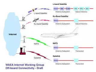
WBS 1.1.3 ReadOut Drivers • Components of the Pixel/SCT Off Detector Electronics • Back Of Crate (BOC) card (optical interface), Cambridge • Read Out Driver (ROD), Wisconsin • Timing Interface Module (TIM), University College London • Crate Backplane, Oxford • SCT DAQ, Cambridge + others to join • Pixel DAQ, Iowa State + others to join • First prototypes of components built and under test individually • Next step(soon) is integrated test of BOC-ROD-TIM
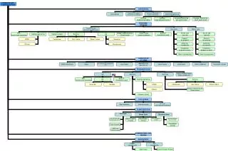
slave DSPs & memories power supplies program FLASH boot FPGA ROD bus buffers router FPGAs event builder FPGA controller FPGA debug & derandomizing memories master DSP & memory dataformatterFPGAs realtimedatapath ROD Prototype
ROD Prototype Status • Preliminary Design Review complete • Two, partially loaded boards received and debugging underway. • Plan to fabricate 6 more with (hopefully) minor modifications after initial debugging complete • Fabrication was delayed(procurement screwup, first bare board vendor failed, parts,…nothing fundamental). • Debugging has gone steadily but somewhat more slowly than planned and is not complete. • No showstoppers yet but also no demonstration all specs met according to documented test plan.
ETC01 Costs • Pixels • Baseline just established. • Silicon Strips • IC test system costs increased(more engineering and more systems) • IC fabrication costs decreased - $ to Euro more favorable(Frame Contract in Euros with Atmel) • Net change compared to ETC00 near 0. • ReadOut Drivers • No calls on contingency - yet. • Production materials costs re-evaluated in July - close to baseline => keep baseline for now until prototype phase complete. • “Working army” costs that might result from delay handled so far. • Net change compared to ETC00 near 0
ETC01 Milestones • Pixels • Baseline just established. • Silicon Strips • Few month delay in start of IC production forecast. Need more irradiation testing. • Module completion date kept same as ETC00 by taking advantage of experience to be gained in coming year, begin construction with detectors+mechanical structure • ReadOut Drivers • Delays in fabrication and debug of prototype propagate into production. • Still appear to have float.
Current Major Risks • Pixels • Cost - more engineering manpower, either from need or from lack of non-project funding • Schedule - integrated circuits • Silicon Strips • Cost - need to compress module assembly time => additional manpower and tooling/equipment • Schedule - IC validation and lack of production planning across collaboration • ReadOut Drivers • Cost - additional engineering if debug of prototype takes too long. • Schedule - same
WBS 1.1 Project Summary • 1.1.1 Pixels • Baseline established. • 1.1.2 Silicon Strips • TPC same as ETC00 baseline • Schedule delays of few months in start of production ICs, currently holding to same completion date for modules as ETC00 baseline. • Need Collaboration-wide production planning to resolve schedule difference between apparent ATLAS need date and our baseline. • 1.1.3 Read-Out Drivers(ROD) • TPC same as ETC00 baseline. • Schedule delays in prototype propagate to production, but float remains in schedule.