Download
1 / 57
580 likes | 817 Vues
CERN-RRB-2006-109 23 rd October 2006 ATLAS Progress Report. Collaboration and management Construction status of the detector systems (Common Projects and installation: see Marzio Nessi’s presentation) Milestones and schedule Brief account on other activities

E N D
CERN-RRB-2006-109 23rd October 2006 ATLAS Progress Report Collaboration and management Construction status of the detector systems (Common Projects and installation: see Marzio Nessi’s presentation) Milestones and schedule Brief account on other activities Computing and physics preparation Status of Completion Planning Conclusions
Collaboration composition Since the last RRB in April 2006 seven Expressions of Interests to join the ATLAS Collaboration have been concluded with unanimous admission votes at the Collaboration Boards of 14th July and 6th October For them the discussions and negotiations for their contributions have been constructive and mutually beneficial This means in particular that in each case necessary technical service tasks and contributions have been identified, besides involvements in physics For a number of other groups we have encouraged them to join forces at this stage with existing ATLAS Institutions (in addition some other contacts have not been pursued) There are no pending Expressions of Interest on the time scale of the April 2007 RRB The Collaboration took also note of the withdrawal of Naruto University of Education, Tokushima, Japan, which has completed its initially expected contribution to ATLAS (GEANT4 development work)
New Institutions unanimously admitted by the ATLAS Collaboration Fachhochschule Wiener Neustadt (FHWN), Wiener Neustadt, Austria (Technical expertize in system integrations, Grid computing) University of Regina, Physics Department, Regina, Canada (Software tools, LAr calibrations and commissioning) DESY (Hamburg and Zeuthen), Germany (HLT, Grid computing, shower simulations) Humboldt University Berlin, Institute of Physics, Berlin, Germany (HLT, commissioning, computing, working very closely with DESY) Nagoya University, Department of Physics, Nagoya, Japan (TGC trigger and DAQ) New York University, Department of Physics, New York, U.S.A. (HLT algorithms for level-2 and EF, commissioning, power systems for upgrades) SLAC, Stanford, U.S.A. (Pixels – hard and software, HLT, simulations, Grid computing) The RRB is kindly requested to endorse the admission of these seven new Institutions in the ATLAS Collaboration
ATLAS Collaboration (As of the October 2006) 35 Countries 164 Institutions 1800 Scientific Authors total (1470 with a PhD, for M&O share) Albany, Alberta, NIKHEF Amsterdam, Ankara, LAPP Annecy, Argonne NL, Arizona, UT Arlington, Athens, NTU Athens, Baku, IFAE Barcelona, Belgrade, Bergen, Berkeley LBL and UC, HU Berlin, Bern, Birmingham, Bologna, Bonn, Boston, Brandeis, Bratislava/SAS Kosice, Brookhaven NL, Buenos Aires, Bucharest, Cambridge, Carleton, Casablanca/Rabat, CERN, Chinese Cluster, Chicago, Clermont-Ferrand, Columbia, NBI Copenhagen, Cosenza, AGH UST Cracow, IFJ PAN Cracow, DESY, Dortmund, TU Dresden, JINR Dubna, Duke, Frascati, Freiburg, Geneva, Genoa, Giessen, Glasgow, LPSC Grenoble, Technion Haifa, Hampton, Harvard, Heidelberg, Hiroshima, Hiroshima IT, Indiana, Innsbruck, Iowa SU, Irvine UC, Istanbul Bogazici, KEK, Kobe, Kyoto, Kyoto UE, Lancaster, UN La Plata, Lecce, Lisbon LIP, Liverpool, Ljubljana, QMW London, RHBNC London, UC London, Lund, UA Madrid, Mainz, Manchester, Mannheim, CPPM Marseille, Massachusetts, MIT, Melbourne, Michigan, Michigan SU, Milano, Minsk NAS, Minsk NCPHEP, Montreal, McGill Montreal, FIAN Moscow, ITEP Moscow, MEPhI Moscow, MSU Moscow, Munich LMU, MPI Munich, Nagasaki IAS, Nagoya, Naples, New Mexico, New York, Nijmegen, BINP Novosibirsk, Ohio SU, Okayama, Oklahoma, Oklahoma SU, Oregon, LAL Orsay, Osaka, Oslo, Oxford, Paris VI and VII, Pavia, Pennsylvania, Pisa, Pittsburgh, CAS Prague, CU Prague, TU Prague, IHEP Protvino, Regina, Ritsumeikan, UFRJ Rio de Janeiro, Rochester, Rome I, Rome II, Rome III, Rutherford Appleton Laboratory, DAPNIA Saclay, Santa Cruz UC, Sheffield, Shinshu, Siegen, Simon Fraser Burnaby, SLAC, Southern Methodist Dallas, NPI Petersburg, Stockholm, KTH Stockholm, Stony Brook, Sydney, AS Taipei, Tbilisi, Tel Aviv, Thessaloniki, Tokyo ICEPP, Tokyo MU, Toronto, TRIUMF, Tsukuba, Tufts, Udine, Uppsala, Urbana UI, Valencia, UBC Vancouver, Victoria, Washington, Weizmann Rehovot, FH Wiener Neustadt, Wisconsin, Wuppertal, Yale, Yerevan
Management and Collaboration Board Following the standard procedures and schedule, the Collaboration Board has elected a new Deputy Collaboration Board Chairperson, who will then become CB Chair afterwards Kerstin Jon-And (Stockholm University) Deputy CB Chair 2007 (and 2010), CB Chair 2008 – 2009 She will replace Siegfried Bethke (MPI Munich) whose term of office finishes at the end of this year The Collaboration Board has also endorsed the re-appointments for the term of office March 2007 to February 2009 for Marzio Nessi Technical Coordinator Markus Nordberg Resources Coordinator The CERN Management has approved formally these appointments Further appointments in managerial positions are included in the following organization chart
Collaboration Board (Chair: C. Oram Deputy: S. Bethke) ATLAS Plenary Meeting Resources Review Board CB Chair Advisory Group Spokesperson (P. Jenni Deputies: F. Gianotti and S. Stapnes) ATLAS Organization October 2006 Technical Coordinator (M. Nessi) Resources Coordinator (M. Nordberg) Executive Board Inner Detector (L. Rossi, K. Einsweiler P. Wells, F. Dittus) Tile Calorimeter (B. Stanek) Magnet System (H. ten Kate) Electronics Coordination (P. Farthouat) Data Prep. Coordination (C. Guyot) Additional Members (H. Gordon, A. Zaitsev) LAr Calorimeter (H. Oberlack, D. Fournier, J. Parsons) Muon Instrum. (G. Mikenberg, F. Taylor, S. Palestini) Trigger/DAQ ( N. Ellis, L. Mapelli) Computing Coordination (D. Barberis, D. Quarrie) Physics Coordination (I. Hinchliffe)
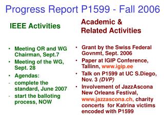
Construction progress of the detector systems (The Common Projects and installation will be covered by M Nessi) ATLAS superimposed to the 5 floors of building 40 Diameter 25 m Barrel toroid length 26 m End-cap end-wall chamber span 46 m Overall weight 7000 Tons
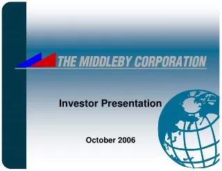
The Underground Cavern at Pit-1 for the ATLAS Detector Side C Side A Length = 55 m Width = 32 m Height = 35 m
Inner Detector (ID) The Inner Detector (ID) is organized into four sub-systems: Pixels (0.8 108 channels) Silicon Tracker (SCT) (6 106 channels) Transition Radiation Tracker (TRT) (4 105 channels) Common ID items
Inner Detector progress summary • Pixels:Barrel layer-2 has been integrated • Low mass Al cables (from modules to first patch panel) had low yield (broken insulator). Solved with new production. Integration schedule tight, but speed is now higher than planned. • Barrel:SCT and TRT barrel integrated in SR1. Tested with cosmics (no x-talk • observed). Installed in the pit. Weighing • demonstrates good understanding of • material. • EC:SCT ECC has been integrated very • recently with TRT ECC after all tests were done on sub-assemblies. SCT ECA is dressing its thermal enclosures and will be ready for integration with TRT by mid November. The schedule is driven by SCT ECA. • The schedule for the Inner Detector remains very tight, without any float left (critical path: Installation and “sign-off” in the pit) Barrel TRT TRT+SCT barrel completed in SR1
ID TRT + SCT barrel tested in SR1 One-eighth of the TRT and one-quarter of the SCT were equipped with complete readout chains Dead channels: 0.2% SCT, 1.5% TRT Noise level as for the individual parts and below specs (e.g. SCT random noise prob. is 4.5 10-5, spec = 5 10-4) No cross talk measured (many trials done) 4 105 cosmics trigger taken TRT %noise occupancy before-after insertion Side view of a cosmic track trough TRT and SCT, noise is small
ID barrel travels to the pit, 24th Aug 2006 A tight fit between BT and EC Calorimeter Through the parking area From the trolley to the support rails Inside cryostat
TRT + SCT integration of EC-C was done end of September, the A side will follow in November ID End-Caps EC-C integration TRT + SCT SCT ECC, in front of its outer thermal enclosure
Pixels All modules have been delivered with good yield Both EC have been integrated, delivered to CERN and acceptance-tested One EC will now go through cosmics tests Barrel stave production did finish mid September (including corrosion leak repairs) Layer-2 has been fully integrated, the two Layer-1 half-shells are finished, and about 1/3 of the B-layer bi-staves assembled The best staves (least dead channels, best thermal performance) are reserved for the b-layer A new potential issue under investigation are failing opto-boards (integrated in service panels) Pixel ECC at CERN, 3 disks visible
Pixel Layer-2 – half shell Pixel Layer2, once clamped, outside Ready for installation date is 1st April 2007 Pixel Layer2, once clamped, inside
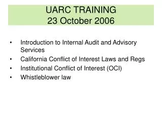
LAr and Tile Calorimeters Tile barrel Tile extended barrel LAr hadronic end-cap (HEC) LAr EM end-cap (EMEC) LAr EM barrel LAr forward calorimeter (FCAL)
Barrel LAr and Tile Calorimeters The barrel calorimeters are in their final position at the centre of the detector since November 2005 The final cool-down of the LAr cryostat took place over April and May 2006 Calorimeter barrel after its move into the center of the detector (4th November 2005)
LAr barrel history over the past months • June: Barrel filled with LAr • Tried burning of a few shorts in the barrel calorimeter in some modules • Results positive on Presampler, essentially no difference on Calorimeter • July: Decide to empty / refill by condensation Refilling operation took 20 days • HV status (at an early stage of commissioning…) • 1600 V on Calorimeter, 2000 V on Presampler, leaving out known problematic channels: • Status on Calorimeter: 2 sectors HV shorts, 10 sectors working with half of the • signal, out of 448 independent sectors • Status on presampler: 7 problems, will try to burn them • Problematic channels: will be dealt with separately • Plans: Leave calorimeter off when not needed, • put 1600 V on 6 – 8 modules needed for cosmics running Stable pressure in expansion vessel Impurity level: Measured with four purity cells: (0.20 +- 0.05) ppm O2 Temperature stability: Tmin = 88.2 K Tmax = 88.6 K Detector sub-cooled between 5.8 K and 8.6 K
End-Cap LAr and Tile Calorimeters The end-cap calorimeters on side C were assembled in the cavern by end of January 2006, and then the end-cap on side A followed in May 2006 Main LAr activities and plans for the end-caps EC-A: - Since August installation of FE electronics (no LVPS yet) - November 2006 start cool down - February 2007 start cold operation EC-C: - Since April installation of FE electronics, then switched to EC-A - February 2007 start cool down - April 2007 start cold operation Completed end-cap calorimeter side C, just before insertion into the detector
Calorimeter electronics LAr FE crate The installation of the LAr Front End (FE) electronics on the detector, as well as of the Back End (BE) read-out electronics in the control room, is proceeding to plans (all production is very close to be finished) A major concern are still the in-time availability, and the reliability of the low and (to a lesser extent) the high voltage LAr power supplies For the Tile Calorimeter, a control problem for the low voltage supplies has been understood, and a corrective action is being implemented (but impact commissioning) Both addressed in detail with the LHCC referees LAr barrel ROD system in USA15
Detailed commissioning work has started… some examples Calibration pulse studies… 0.1-0.2 % amplitude stability over one month Muons in cosmics… First high energy ionization signal Noise studies…… day to day work to track coherent noise S/B =11 No increase of coherent noise when solenoid field is on
Event display from the first LAr + Tile Calorimeter barrel cosmics run Correlation between LAr Middle & Front layer
Muon Spectrometer Instrumentation The Muon Spectrometer is instrumented with precision chambers and fast trigger chambers A crucial component to reach the required accuracy is the sophisticated alignment measurement and monitoring system Precision chambers: - MDTs in the barrel and end-caps - CSCs at large rapidity for the innermost end-cap stations Trigger chambers: - RPCs in the barrel - TGCs in the end-caps At the end of February 2006 the huge and long effort of series chamber production in many sites was completed for all chamber types
Barrel Muon Chamber installation: Almost 80 % installed today Extrapolation assumes 3.7 chambers per day. The main problem has been access and crane availability, more than chamber availability or the actual installation of the chambers on the rails Lots of detailed small problems need to be solved inside the detector when moving the chambers to their final positions: services out of envelope, poor access, scaffolding in front of the chambers, etc.
August 2006 saw the first combined MDT + RPC + Tile Calorimeter cosmic ray muon run RPC trigger on sector-13
Assembly of End-Cap Big Wheel sectors in Hall 180 Assembly progress in 2006: • Sectors for TGC-1-C: completed by April 7 (~10 days/sector in 2006) • Sectors for MDT-C: completed by May 23 (~12 days/sector in 2006) • Sectors for TGC-2-C: completed between May 1 and Aug 29 (7 days/sector over most of the assembly period) • Sectors for MDT-A finished within few weeks, TGC-3-C well advanced There are in total for both sides 6 TGC and 2 MDT Big Wheels, requiring 72 TGC and 32 MDT sectors
First TGC ‘Big-Wheel’ assembled in the cavern early September 2006
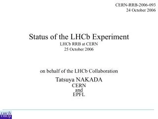
SDX1 dual-CPU nodes CERN computer centre ~30 ~1600 ~100 ~ 500 Local Storage SubFarm Outputs (SFOs) Event Filter (EF) Event Builder SubFarm Inputs (SFIs) LVL2 farm Event rate ~ 200 Hz Data storage pROS DataFlow Manager Network switches stores LVL2 output Network switches LVL2 Super- visor Event data pulled: partial events @ ≤ 100 kHz, full events @ ~ 3 kHz ATLAS Trigger / DAQ Data Flow Second- level trigger SDX1 pROS stores LVL2 output Event data requests Delete commands Gigabit Ethernet Requested event data USA15 Regions Of Interest USA15 Data of events accepted by first-level trigger 1600 Read- Out Links UX15 ~150 PCs VME Dedicated links Read- Out Drivers (RODs) ATLAS detector Read-Out Subsystems (ROSs) RoI Builder First- level trigger UX15 Timing Trigger Control (TTC) Event data pushed @ ≤ 100 kHz, 1600 fragments of ~ 1 kByte each
Level-1 The level-1 system (calorimeter, muon and central trigger logics) is in the production and installation phases for both the hardware and software The muon trigger sub-system faces a very tight schedule for the on-chamber components as reported before, but is proceeding satisfactorily
Installation in the underground counting room is in progress Cabling, patch panels, tests with test-pulse signals from calorimeters, etc. Also integration with DAQ, HLT and LVL1 CTP Full-crate tests of pre-production modules are almost completed Preprocessor & ROD modules are the most schedule-critical items Most modules now in production Pre-Processor 1/8 Analogue signalcables in USA15 Cluster Processor 1/4 Tile calorimeter test-pulse signal recorded through LVL1 Pre-processor LVL1 calorimeter trigger
Barrel Trigger Sector 13:Extrapolation of RPC cosmic-ray tracks to ground level ATLAS shafts TGC detectors with on-detectortrigger electronics in cavern LVL1 muon trigger Trigger rate ~60 Hz consistentwith simulation of cosmic rays incorresponding configuration
HLT/DAQ/DCS The High Level Trigger (HLT), Data Acquisition (DAQ) and Detector Control System (DCS) activities have continued to proceed according to plans Large scale system tests, involving up to 800 nodes, have further demonstrated the required system performance and scalability Scalability is particularly important for staging needs during the initial running of ATLAS A major emphasis was put on all aspects of the HLT and DAQ software developments Example of performance optimization Components of the DCS are in fabrication or already finished (ELMB), and are already widely used, and the s/w components are available The DCS is one of the first systems already in operation at Pit-1
Installation & commissioning - Read-Out System All 153 ROSs installed and standalone commissioned • Each ROS PC is equipped with the final number of ROBIN cards (700 in total including spares) ROBIN 44 of them connected to RODs and fully commissioned • These are the full LAr-barrel, 1/2 of Tile and the CTP • Taking data regularly with final DAQ • Event building at the ROS level using the control network Commissioning of other detector read-outs driven by RODs installation • Expect to complete most of it by end 2006
DAQ/HLT pre-series system • Pre-series system at Point-1 continues to be extensively used • For measurements, assessment and validation • HLT algorithms started to be used as well • Thanks to substantial progress in complex software integration process • Using physics data-sets pre-loaded in ROSs • Egamma, muon, tau and jet algorithms have been integrated for the first time online (release 11.0.6) • “24-hr” DAQ/HLT-runs regularly organised • Use full chain as if it was an ATLAS run • Force to focus on operational issues • Increase expertise • Reveal problems not seen on sub-system testing Extremely valuable!
Installation & commissioning - SDX1 (surface HLT/DAQ room) A total of ~100 racks / 2500 highest-performance multi-core PCs in final system- First 50 machines of Event Builder and HLT infrastructure are being installed - First 4 HLT racks (~120 computing nodes) follow in early 2007
LHCC milestones evolution • Construction issues and risks (‘Top-Watch List’) • A list of these issues is monitored monthly by the TMB and EB, and it is publicly visible • on the Web, including a description of the corrective actions undertaken: • http://atlas.web.cern.ch/Atlas/TCOORD/TMB/
ATLAS Installation Activities (Working Schedule) - Beam pipe in place end of August 2007 - Restricted access to complete end-wall muon chambers and global commissioning until Nov 2007 - Ready for collisions from Nov 2007
Commissioning plans (overview) • Integration of experiment • Global aim:ATLAS operational in summer 2007 • First milestone: initial ATLAS core operational in fall 2006 • Participants • Barrel calorimeters (with at least a minimal geometry) • DAQ • Central DCS • Online DataBases • Control room • Common trigger using TTC, LTP, CTP • Additional “ingredients” • Monitoring system, “combined” monitoring • A cosmic trigger for real particles in the detector • Offline analysis
ATLAS forward detectors Being developed since the encouragements after the LHCC LoI CERN/LHCC/2004-010: Roman Pots: Absolute luminosity measurement LUCID: Cherenkov light luminosity monitor LoI to be submitted to the LHCC after the internal review is concluded (aim for February 2007): Zero Degree Calorimeter (ZDC) Instrumentation of the TAN for HI physics and beam tuning (Working contacts with LHCf) Future evolutions, to pass through ATLAS first, and then LHCC: Integration of so-called ‘FP420’ (the ATLAS participants) into the ATLAS forward detector and physics programme Note: ATLAS forward detector and physics efforts are treated as an integral part of ATLAS in all aspects
ATLAS organization to steer R&D for upgrades ATLAS has put in place a structure to steer its planning for future upgrades, in particular for R&D activities needed for possible luminosity upgrades of the LHC (‘SLHC’) The main goals are to Develop a realistic and coherent upgrade plan addressing the physics potential Retain detector experts in ATLAS with challenging developments besides detector commissioning and running Cover less attractive (but essential) aspects right from the beginning The organization has two major coordination bodies Upgrade Steering Group (USG) (Existing since June 2004, with representatives from systems, software, physics, and relevant Technical Coordination areas) Project Office (UPO) (New body, fully embedded within the Technical Coordination)
Areas to be addressed by Upgrade Project Office • overall mechanical design, drawings and layout control • Reviews and R&D follow-up • planning of services • electronics coordination • installation scenarios, scheduling • radiation, shielding, activation • interface to machine Engineers/technicians in project office are expected to be part-time active in ATLAS operations Define work packages to be taken up by groups outside of CERN (under project office coordination) ATLAS SLHC R&D projects There is a reviewing and approval procedure in place, and first proposals have been internally approved, and others are in the pipe-line There is good communication with CMS upgrade studies to benefit from common approaches However, there is no ambiguity, ATLAS’ priority is to complete, commission and exploit the TDR detector !
2003 • POOL/SEAL release (done) • ATLAS release 7 (with POOL persistency) (done) • LCG-1 deployment (done) • ATLAS complete Geant4 validation (done) • ATLAS release 8 (done) • DC2 Phase 1: simulation production (done) • DC2 Phase 2: intensive reconstruction (done) • Combined test beams (barrel wedge) (done) • Computing Model paper (done) • Computing Memorandum of Understanding (done) • ATLAS Computing TDR and LCG TDR (done) • Start of Computing System Commissioning (in progress) • Physics Readiness Documents (re-scheduled: early 2007) • Start cosmic ray run • GO! 2004 2005 2006 2007 ATLAS Computing Timeline
The computing and software suite has progressed on a very broad front, with a • particular emphasis to make it as accessible as possible to the user community • Examples: GRID production tools • Software infrastructure • Detector Description and graphics • Framework and Event Data Model • Simulation • Tracking (ID and Muons) and calorimeters (LAr and Tiles) • Database and data management • Reconstruction and Physics Analysis tools • Distributed analysis • Computing System Commissioning (CSC) along sub-system tests with • well-defined goals, preconditions, clients and quantifiable acceptance tests • Examples: Full Software Chain • From generators to physics analysis • Tier-0 Scaling • Calibration & Alignment • Trigger Chain & Monitoring • Distributed Data Management • Distributed Production (Simulation & Re-processing) • (Distributed) Physics Analysis • General ‘rehearsal’ of TDAQ/Offline data flow and analysis • ATLAS computing is fully embedded in, and committed to, the WLCG framework • Special issues have been addressed in task forces • Examples Luminosity block structure • Data Streaming Model
Example 1: daily production jobs over the past couple of months Production for software validation and CSC physics samples Some statistics June now: Over 50 Million events produced EGEE grid 59 % NorduGrid 13 % OSG 28 %
Example 2: data flow tests over the past few months DDM Operations: T0->T1’s Data flow to 9 Tier-1’s No direct data flow from T0 to Tier-2’s (ATLAS Computing Model) NorduGrid to be integrated into Distributed Data Management (DDM) system Total data copied so far: 1.6 PB (1 PB = 10^15 Bytes) DDM is critical, and needs full functionality urgently
CB Publication Committee, Speaker Committee ATLAS management: SP, Deputy SP, RC, TC Collaboration Management, experiment execution, strategy, publications, resources, upgrades, etc. TMB Executive Board Physics (Physics Coordinator) optimization of algorithms for physics objects, physics channels Detector Operation (Run Coordinator) Detector operation during data taking, online data quality, … Data Preparation (Data Preparation Coordinator) Offline data quality, first reconstruction of physics objects, calibration, alignment (e.g. with Zll data) Computing (Computing Coordinator) Core Software, operation of offline computing, … Trigger (Trigger Coordinator) Trigger data quality, performance, menu tables, new triggers, .. (Sub)-systems: Responsible for operation and calibration of their sub-detector and for sub-system specific software Figure 2 Operation Model (Organization for LHC Exploitation) (Details can be found at http://uimon.cern.ch/twiki//bin/view/Main/OperationModel ) The DP activity is now starting within the context of the Operation Model
In Release 12.0.3 (current) Example of preparations towards the physics exploitation: Calibration Data Challenge (CDC) G4-simulation of calibration samples [O(10M) events, e.g. Z ll] Geometry of “as-installed mis-aligned” detector Reconstruction pass N (Release 13, Feb. 07) Analysis Calib/align constants from pass N-1 Calib/align constants pass N Pass 1 assumes perfect calibration/alignment and nominal material Condition DataBase • Obtain final set of corrections, alignment and calibration constants • Compare performance of “as-installed mis-aligned” detector after calibration and alignment to nominal (TDR) performance • Exercise (distributed) infrastructure: Condition DB, bookkeeping, etc. • A blind test: learn how to do analysis w/o a priori information • 24h latency test: calibration constants for 1st pass data reconstruction at Tier0
Looking further ahead: ‘The Dress Rehearsal’ A complete exercise of the full chain from trigger to (distributed) analysis, to be performed in 2007, a few months before data taking starts Some details for experts: • Generate O(107) evts: few days of data taking, ~1 pb-1 at L = 1031 cm-2 s-1 • Filter events at MC generator level to get physics spectrum expected at HLT output • Pass events through G4 simulation (realistic “as installed” detector geometry) • Mix events from various physics channels to reproduce HLT physics output • Run LVL1 simulation (flag mode) • Produce byte streams emulate the raw data • Send raw data to Point 1, pass through HLT nodes (flag mode) and SFO, write out events by streams, closing files at boundary of luminosity blocks. • Send events from Point 1 to Tier0 • Perform calibration & alignment at Tier0 (also outside ?) • Run reconstruction at Tier0 (and maybe Tier1s ?) produce ESD, AOD, TAGs • Distribute ESD, AOD, TAGs to Tier1s and Tier2s • Perform distributed analysis (possibly at Tier2s) using TAGs • MCTruth propagated down to ESD only (no truth in AOD or TAGs) Ambitious goals… need to plan it carefully (both in terms of effort needed and of technical issues and implications)
Physics Coordination started to address goals of the 2007 run Interaction rate ~10kHz s =900 GeV, L = 1029 cm-2 s-1 Jets pT > 15 GeV (b-jets: ~1.5%) Jets pT > 50 GeV Jets pT > 70 GeV J/ W e, Z ee, 30 nb-1 100 nb-1 + 1 million minimum-bias/day 30% data taking efficiency included (machine plus detector) Trigger and analysis efficiencies included • Start to commission triggers and detectors with LHC collision data (minimum bias, jets, ..) • Maybe first physics measurements (minimum-bias, underlying event, QCD jets, …) ? • Observe a few W l, , J/ ?