Download
1 / 58
580 likes | 794 Vues
design of solar cooling device enhanced with evacuated tube and radiation concentrator by: Ahmad Bahar Amjad Fattouh Jafar Masri Karam Rezeq Superviser : Dr. Abdelrahim Abusafa. Content. Project Overview.

E N D
design of solar cooling device enhanced with evacuated tube and radiation concentrator by: Ahmad BaharAmjadFattouhJafarMasriKaramRezeq Superviser:Dr. AbdelrahimAbusafa
Project Overview • Today, our energy system is based on extracting highly concentrated forms of energy we find in nature, such as fossil fuels, large rivers and waterfalls, and burning trees. • Most regions, particularly developing countries are experiencing significant energy demand growth which puts pressure on global energy sources.
In general, the practice of extracting naturally concentrated energy causes 4 interrelated fundamental problems: Disrupting natural energy flows, Depletion, Centralization, and Resource wars. • Unfortunately, our energy system is dysfunctional because highly concentrated forms of energy specially fossil fuels are in short supply and play critical roles in damaging the environment.
Moreover, fossil fuels that are widely used today are harmful for the environment. In the early seventies and eighties there were people and even scientist who preach otherwise, but today the negative effects are showing.
Global Warming: • Global warming is the rise in the average temperature of earth's atmosphere and oceans since the late 19th century and its projected continuation. • This means that the surface temperature of the earth increases by 0.6°C ± 0.2°C over the last century. This may not sound like much, but the warming will increase with time, and could have disastrous consequences.
Sea level rise • Impacts on agriculture • Reduction of the ozone layer • Increased extreme weather • Spread of diseases
These will impact some of the world's poorest and most vulnerable people, disrupting food production, and threatening vitally important species, habitats and ecosystems.
Project Objectives 1- Investigate the solar energy cooling systems and applications: • Review the history of solar energy applications. • Review the available literature on solar energy and its use. • Look at the potential use of solar energy in Palestine. 2- Illustrate the solar heating collectors such as evacuated tubes and flat plate collectors. 3- Design and construct a solar refrigeration system that works with almost no maintenance requirements and can be used in remote areas to store food and medicine.
The main goal is to examine a potential source of energy that is cheap, available, affordable, renewable and most important environmentally friendly.
Over 1.2 billion people - 20% of the world's population - are still without access to electricity worldwide, almost all of whom live in developing countries. • Here in Palestine, many countries specially remote communities in Al-Naqab Desert, Tubas, Jericho, Hebron and Jenin are still without any access to electricity due to the Israeli occupation and lack of funding.
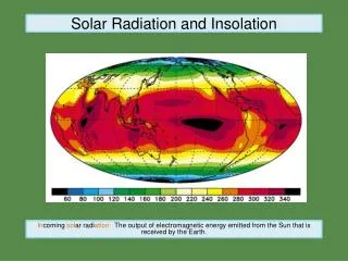
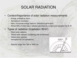
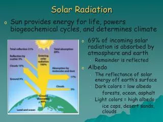
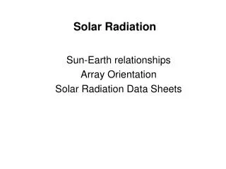
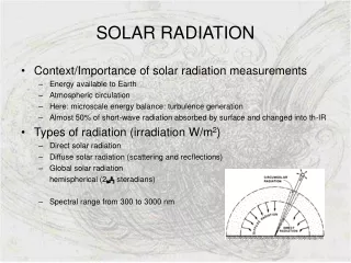
Solar Energy Cooling • Solar energy refers primarily to the use of solar radiation and heat from the sun. • Solar energy technologies include solar cooling solve some of the most important energy problems the world now faces. • Every day enough solar energy reaches the earth to fulfill our needs, and this energy should be exploited and considered as an important energy source.
Solar energy can be a major contributor to the future Palestinian energy supply, with its high potential in the area. Palestine receives about 3,000 hours of sunshine per year and has an average solar radiation of (5.46 kWh/m².day).
Solar Adsorption Cooling • In areas of the world where there is no reliable electricity supply to power conventional refrigerator systems and where there is a high potential of solar energy, the use of solar powered adsorption refrigerators are particularly interesting. • It could be used in developing countries for the storage of vaccine (medical products) and food such as vegetables and meat.
The solar adsorption refrigerator is mainly composed of a collector containing the adsorbent, an evaporator and a condenser. It uses the performances of the pair adsorbent–refrigerant, during adsorption and desorption, within the operation of the refrigerator.
System Description • The next slides will describe the device constructed, the working principle of the device and it’s components.
Working Principle: • On a sunny day, the collector absorbs solar radiation energy, which raises the temperature of the evacuated tube bulb, the heat transfers from the bulb to the adsorbent by conduction. • When the temperature of adsorbent reaches the desorption temperature, the refrigerant begins to evaporate and desorbs from the bed. The desorbed refrigerant vapor condenses into liquid via the condenser and flows into the evaporator directly.
During night, when the temperature of the adsorbent bed decreases, the refrigerant begins to evaporate by absorbing heat from the water to be frozen and is adsorbed by the adsorbent in the bed.
Components of the System: • The main components of the solar cooling device are: • The Adsorbent Bed (Generator) • The Solar Collector (Evacuated Tube) • The Radiation Concentrator • The Condenser • The Manifold • The Evaporator
1- Adsorbent Bed: • Adsorbent bed or the generator is a stainless steel pipe with 12.5 cm diameter and 1.5 m in length. • It contains the adsorbent (activated carbon) and it has holes to connect with both the manifold and the bulb of the evacuated tube which is the heat source for activated carbon.
Activated Carbon: • Activated carbon is the adsorbent in the system, and its location in the system is the bed. • The amount that added was 14.7 kg.
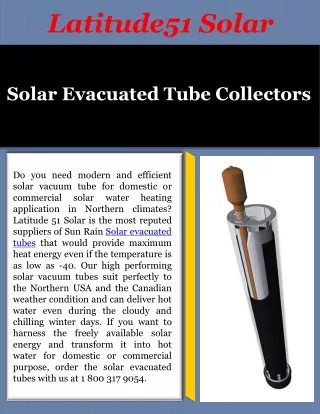
Eight evacuated tubes were used, each of them compound from two coaxial tube, the outer tube clearly but the internal one coated with selective absorber material, and the space between them was vacuum to reduce or eliminate the heat loss from the fluid in the internal tube. • Solar energy passes through outer tube and absorbed by the internal one then it transfer to the copper bulb as follow:
3- Radiation Concentrator: • Parabolic trough concentrators made of reflective stainless steel were used to maximize the amount of energy applied to the evacuated tubes and controlling the distribution of sun rays. • They have the dimensions of : 175 cm long, 27 cm arc length.
Design of the Concentrator: • We start by considering the parabola. • The equation of a parabola is: y = a.x² • For a parabola with a focal length of f, a= 1/(4f), so the equation and the curve will be :
We have applied the equation y=x²/4f, with a focal point of 7 cm.
4- Condenser: • To facilitate the cooling of the condenser, stainless steel tubes with four fins were designed and permitted to maximize the heat exchange area with the ambient.
5- Manifold: • The adsorbent bed, the condenser and the evaporator were connected with each other by using stainless steel pipes of 0.75 inch diameter. • All of the pipes that have been used in the system were made of (304 stainless steel) type to avoid dissociating the methanol.
6- Evaporator: • In order to enhance the heat transfer effect, the heat exchange surface is designed as a series of four trapezoidal cells. • the dimensions of the evaporator is 220×320×100 mm3, and the heat exchange area is about 0.28m2. • The evaporator is partially immersed in a water tank, which is made of Stainless steel and both the evaporator and water tank are placed in insulated box covered with insulation.
Methanol : • Methanol is the refrigerant in the system and it has been charged into the system through the pressure valve after vacuum . • The density of methanol is 0.7918 kg/L and theoretically every 1 kg of activated carbon adsorbs 0.45 kg methanol, based on these data the amount of methanol needed as we have 14.7 kg activated carbon is 8.317 L, but the amount of methanol used was 10 liters, because the activated carbon might not release the whole amount of methanol adsorbed.
Results and Discussion • The device has been constructed through the summer and unfortunately finished in October, 2013 when the weather wasn’t in the desired condition. • Experiments were conducted using electrical heaters to simulate the solar heating.
The data of the system were recorded using Lutron Measurement System software downloaded on a computer and connected to a thermometer. • The heat collected by the evacuated tubes is: 0.7*5.4*2.7*1000/10 = 1020.6 watt • Every heater has a power of 250 watt, and we have used four electric heaters, so 1000 watt of heat have been used to simulate the heat from the sun.
Change in Pressure Gauge: • As the temperature of the bed increase the pressure inside the system increase and that is due to releasing the methanol from the activated carbon as vapor. • And during the night, the pressure inside the system increase also due to the evaporation of methanol at the room temperature.
Results of Six Hours Heating: • The cycle of heating began at a bed temperature of 28 °C, evaporator temperature of 18.2 °C and water temperature of 18.5 °C. • Heating ended at a bed temperature of 104.7 °C, evaporator temperature of 22.4 °C and water temperature of 23 °C.
Results of Cooling: • The cycle of cooling began at a bed temperature of 104 °C, evaporator temperature of 24.7 °C and water temperature of 25 °C. • Cooling ended at a bed temperature of 28 °C, evaporator temperature of 9 °C and water temperature of 9.4 °C.
Coefficient of Performance: • Q = C*m*ΔT Where: Q: heat loss from water (in joule). c: specific heat of water = 4.18 kJ/kg.K. m: mass of water = 9 kg ( as tested). ΔT: temperature difference of water from the beginning of adsorption to the end of adsorption (in K). • Qwater = 4.18*9*[(25 – 9.4) + 273] = 10857 kJ • Qheaters = 1000*6*3600/1000 = 21600 kJ • COP= Qwater/Qheaters • COP= 10857 / 21600 = 0.502