Download
1 / 67
710 likes | 980 Vues
Objective of Computer Vision. • The field of computer vision can be divided into two areas – Image enhancement – Image analysis. Here we concentrate on fast methods typical for robot soccer and robot theatre applications. Binary image processing. Image with two gray levels 0 and 1

E N D
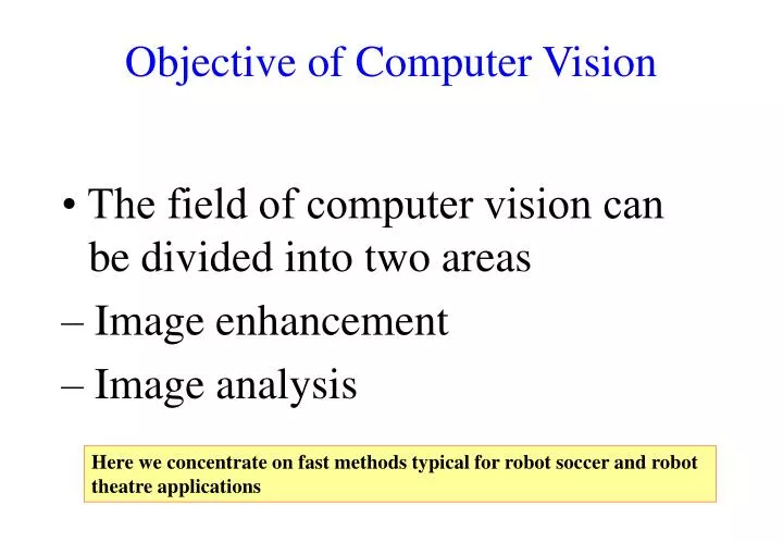
Objective of Computer Vision • The field of computer vision can be divided into two areas – Image enhancement – Image analysis Here we concentrate on fast methods typical for robot soccer and robot theatre applications
Binary image processing • Image with two gray levels 0 and 1 • It contains the basic terms and concepts used in machine vision. • Its techniques are used in all aspects of a vision system. • Small memory requirements • Fast execution time
Region and segmentation • Region ( ) • A subset of an image • Segmentation • Grouping of pixels into regions such that
Thresholding • Thresholding : • A method to convert a gray scale image into a binary image for object-background separation • : Thresholded gray image • Obtained using a threshold T for the original gray image . • : Binary image • Equivalent to .
Three types of thresholding where Z is a set of which elements are integer-valued intervals.
Image notation for soccer • Image : a two-dimensional array of pixels Pixel a[i, j]
Geometric properties • In many cases, some simple features of regions are useful to: • determine the locations of objects, • and to recognize objects. • Geometric properties: • Size • Position • Orientation
Size and position • Given an m x n binary image, • Size (area) A : zero-order moment • Position : the center of area Total size is number of black dots Average in x Average in y
How to calculate line orientation? Step 1: calculate a,b,c coefficients • The center of object : • Let • By the least-squares fit of the line, Step 2: calculate angle, line orientation
Size filter for Noise removal • It can effectively remove noise after component algorithm labeling. • If objects of interest have sizes greater than T, all components below Tare removed by changing the corresponding pixels’ values to 0. A noisy binary image and the resulting image after size filtering (T = 10)
How to get the position and angle of robot • Get frame-grabber, color CCD camera and computer. • Understand how you can read the image data from frame-grabber. • Find the position of a colored object in 2-D image. • Determine the robot uniform with two colored objects • Calculate the position and angle of the robot from the positions of two colored objects.
Position of colored object 1. Setting of ranges for YUV • [Ymin,Ymax], [Umin,Umax], [Vmin, Vmax] 2. Thresholding 3. Labeling (grouping) 4. Size filtering (noise elimination) 5. Finding the center of a colored object
Robot position and heading This cross sign is easy to recognize
Robot color and team color This slide explains labeling robots and teams
Window tracking method • Processing only the data within a small window • Getting a fast vision processing
Line Orientation • Orientation from of the axis of elongation This is called line orientation
Line equation : • : the minimum distance between the line and origin • : the angle from x-axis to the line • The distance, d, from any (x, y) within the object to the line : • which satisfies • Minimize Our task is to find values of angle theta and rho for which this formula is minimum. This provides best fit to line equation
Given is object. Find its line orientation • The center of object : • Let • Calculate center • Calculate a, b, and c.
By the least-squares fit of the line, • Calculate center • Calculate a, b, and c. • Calculate theta
Binary algorithms • Several definitions • Neighbors • 4-neighbors (4-connected) • 8-neighbors (8-connected)
Path • A sequence of neighbors • Foreground : • The set of all unity valued pixels in an image • Connectivity • A pixel is said to be connected to if there is a path from to consisting entirely of pixels of . • Connected components • A set of pixels in which each pixel is connected to all other pixels.
Component labeling • Component labeling algorithm • It finds all connected components in an image and assigns a unique label to all the points in a component. • One of the most common operations in machine vision • Recursive connected components algorithm • Sequential connected components algorithm • The points in a connected component form a candidate region for an object.
Recursive algorithm for connected component labeling • Recursive connected components algorithm • Scan the image to find an unlabeled unity valued pixel and assign it a new label L. 2. Recursively assign a label L to all its unity valued neighbors. 3. Stop if there are no more unlabeled unity valued pixels. 4. Go to step 1.
Sequential algorithm for connected component labeling • Sequential connected components algorithm using 4-connectivity • Scan the image from left to right and top to bottom. 2. If the pixel is unity valued , then • If only one of its upper or left neighbors has a label, then copy the label. (b) If both have the same label, then copy the same label. (c) If both have different labels, then copy the upper pixel’s label and enter the labels in an equivalence table as equivalent labels.
Sequential algorithm for connected component labeling continued (d) Otherwise assign a new label to this pixel and enter this label in the equivalence table. 3. If there are more pixels to consider, then go to step 2. 4. Find the lowest label for each equivalent set in the equivalence table. 5. Scan the picture. Replace each label by the lowest label in its equivalent set.
Digital Geometry Pixel value I(I,j) = j I(i,j) (0,0) • Neighborhood • Connectedness • Distance Metrics Picture Element or Pixel i 32 0,1 Binary Image 0 - K-1 Gray Scale Image Vector: Multispectral Image
Connected Components • Binary image with multiple 'objects' • Separate 'objects' must be labeled individually 6 Connected Components
Finding Connected Components P1 P3 P2 P4 connected to connected to P2 P3 P4 P1 P1or P2 P3or P4 P1or P2 P3or P4 not connected to not connected to not connected to not connected to • Two points in an image are 'connected' if a path can be found for which the value of the image function is the same all along the path.
Algorithm • Pick any pixel in the image and assign it a label • Assign same label to any neighbor pixel with the same value of the image function • Continue labeling neighbors until no neighbors can be assigned this label • Choose another label and another pixel not already labeled and continue • If no more unlabeled image points, stop. Who's my neighbor?
Neighbor • Consider the definition of the term 'neighbor' • Two common definitions: Four Neighbor Eight Neighbor • Consider what happens with a closed curve. • One would expect a closed curve to partition the plane into two connected regions.